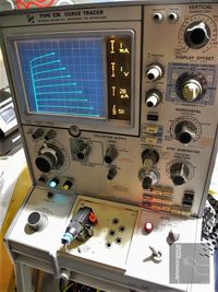
Tektronix Type 576 Curve-Tracer
From a local industrial measurement equipment reseller I acquired a vintage non functional Tektronix Type 576 Curve-Tracer (first series, manufactured by Tektronix Holland N.V. /Heerenveen in the Netherlands) including several test-fixture units but no component test-adapters. The unit had to be serviced as described below.
Adjustment
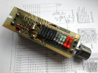
To adjust the TEK576 Curve-Tracer, the Calibration Fixture (TEK067059900) has to be used. It provides calibration voltages and currents for the horizontal- and vertical deflection units of the TEK576. In addition, it contains current-loads for testing the collector supply and step generator. Because this unit was not available, it had to be substituted. Luckily, I was able to find a manual for the calibration unit, containing schematics and circuit description. Although complex, circuit parts, which had to rebuild, could be identified. The circuit provides synchronous pulses of +25V and 0.5V as well as a synchronous 0.5V saw-tooth signal. In addition, a service jack and switch was added to the TEK576, to connect the pulse source and other DC calibration signals.
HV-Range Reactivation
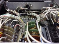
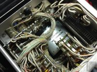
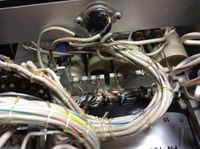
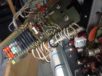
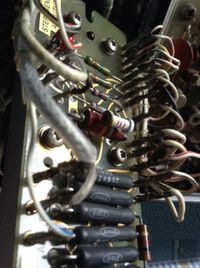
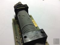
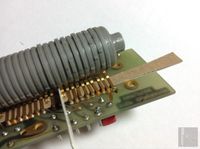
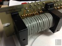
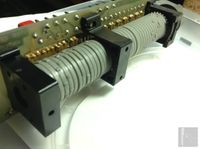
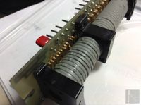
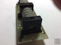
When I first acquired the TEK576 Curve-Tracer (which was manufactured by TEK Netherlands around 1974) the high-voltage (HV) ranges had been partially deactivated by the previous owner, as marked by a sticker. To reactivate the high-voltage, it was necessary to partially dismantle the collector voltage switch unit, which was quite complicated and took a long time. Soldering points were hidden or blocked by other parts. Nevertheless, the HV could be brought back to full functionality.
Faulty HV-Transformer
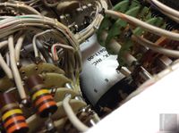
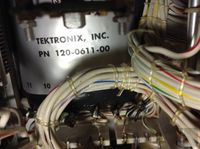
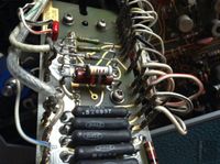
The HV transformer of the early production TEK576 Curve-Tracers contains an isolation compound which is hygroscopic. This leads to high losses and excessive currents within the HV circuit, causing the power supplies over-current protection circuit to switch off. Because there was nothing to loose, I tried to carefully remove the brown sticky wax-like compound. Because the inner construction was unknown, layer by layer was removed using a small knife and pliers. Special care was necessary to not cut the thin wires of the HV winding. After all compound was removed, the windings have been covered by insulation enamel. In addition, the ferrite core next to the winding have been covered by isolation-tape. In the finished reassembled HV circuit, no spark-overs have been noticed, even when the transformer is not entirely encapsulated by compound. The resulting HV and currents are now within tolerances.
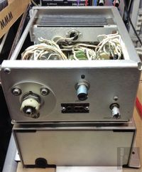
To archive additional cooling, a small fan was added to the cover of the HV compartment as shown in the pictures. The 12V van is operated via a current limiting resistor with lower speed.
Step Generator Amplitude Switch
Additional descriptions under construction!
Readout Display
Additional descriptions under construction!
Variable Sweep Voltage Converter
Additional descriptions under construction!
Readout PCB LED Conversion
Additional descriptions under construction!
Readout LED Light-Pipe
Additional descriptions under construction!
PE Indicator & Line-Connector
Additional descriptions under construction!
Additional descriptions under construction!
Main PCBs
Additional descriptions under construction!
PCB Hinge
Additional descriptions under construction!
Noise Trimmer-Capacitor
Additional descriptions under construction!
LV-Regulator PCB
Additional descriptions under construction!
Indicator Lamps LED Conversion
Additional descriptions under construction!
Graticule Lamps LED Conversion
Additional descriptions under construction!
Dispaly Switching PCB
Additional descriptions under construction!
CRT
Additional descriptions under construction!
Self-Made Photo Adaptor
Additional descriptions under construction!




![[000146]_WZ](/.cm4all/uproc.php/0/TEK576/TEK576_Indicator-Lights_WZ/.%5B000146%5D_WZ.jpg/picture-200?_=1716b04a230)
![[000148]_WZ](/.cm4all/uproc.php/0/TEK576/TEK576_Indicator-Lights_WZ/.%5B000148%5D_WZ.jpg/picture-200?_=1716b04a230)
![[000149]_WZ](/.cm4all/uproc.php/0/TEK576/TEK576_Indicator-Lights_WZ/.%5B000149%5D_WZ.jpg/picture-200?_=1716b049678)
![[000161]_WZ](/.cm4all/uproc.php/0/TEK576/TEK576_Indicator-Lights_WZ/.%5B000161%5D_WZ.jpg/picture-200?_=1716b049a60)
![[000012]_WZ](/.cm4all/uproc.php/0/TEK576/TEK576_CRT_WZ/.%5B000012%5D_WZ.jpg/picture-200?_=1716aff1c20)
![[000013]_WZ](/.cm4all/uproc.php/0/TEK576/TEK576_CRT_WZ/.%5B000013%5D_WZ.jpg/picture-200?_=1716aff1450)
![[000014]_WZ](/.cm4all/uproc.php/0/TEK576/TEK576_CRT_WZ/.%5B000014%5D_WZ.jpg/picture-200?_=1716aff1450)
![[000018]_WZ](/.cm4all/uproc.php/0/TEK576/TEK576_CRT_WZ/.%5B000018%5D_WZ.jpg/picture-200?_=1716aff0898)
![[000017]_WZ](/.cm4all/uproc.php/0/TEK576/TEK576_CRT_WZ/.%5B000017%5D_WZ.jpg/picture-200?_=1716aff1068)
![[000016]_1_WZ](/.cm4all/uproc.php/0/TEK576/TEK576_CRT_WZ/.%5B000016%5D_1_WZ.jpg/picture-200?_=1716aff0c80)
![[000015]_WZ](/.cm4all/uproc.php/0/TEK576/TEK576_CRT_WZ/.%5B000015%5D_WZ.jpg/picture-200?_=1716aff1068)
![[000019]_WZ](/.cm4all/uproc.php/0/TEK576/TEK576_CRT_WZ/.%5B000019%5D_WZ.jpg/picture-200?_=1716aff04b0)
![[000020]_WZ](/.cm4all/uproc.php/0/TEK576/TEK576_CRT_WZ/.%5B000020%5D_WZ.jpg/picture-200?_=1716aff04b0)
![[000021]_WZ](/.cm4all/uproc.php/0/TEK576/TEK576_CRT_WZ/.%5B000021%5D_WZ.jpg/picture-200?_=1716afef8f8)
![[000022]_WZ](/.cm4all/uproc.php/0/TEK576/TEK576_CRT_WZ/.%5B000022%5D_WZ.jpg/picture-200?_=1716afef8f8)
![[000025]_WZ](/.cm4all/uproc.php/0/TEK576/TEK576_CRT_WZ/.%5B000025%5D_WZ.jpg/picture-200?_=1716afef128)
![[000024]_WZ](/.cm4all/uproc.php/0/TEK576/TEK576_CRT_WZ/.%5B000024%5D_WZ.jpg/picture-200?_=1716afef128)
![[000023]_WZ](/.cm4all/uproc.php/0/TEK576/TEK576_CRT_WZ/.%5B000023%5D_WZ.jpg/picture-200?_=1716afef128)
