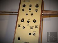
Claravox Centennial (CV-C) Theremin
Review & Improvement
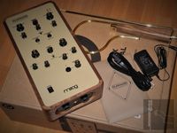
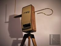
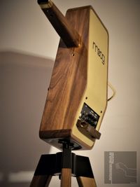
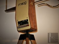
The Claravox Centennial (CV-C) Theremin (Claravox is a trademark of Moog Music, Inc.) has arrived in September 2021. The delivery had been delayed by approximately eight months, so it was supposed that the instrument would work as expected after such a long preparation time.
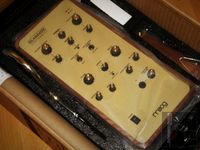
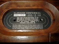
Unfortunately, the Moog Claravox Centennial Theremin #00185 suffers from issues which will be described below. Probably, some of them may have been fixed already by an update of the Theremin firmware and hardware at later shipment dates.
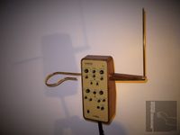
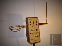
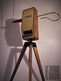
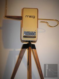
The CV-C Theremin is intended to be placed at a dedicated Claravox Stand which must be purchased separately. This stand has issues, too.
Please note the following: Most of the proposed remedies for improving the Claravox Centennial Theremin or even making it operational as intended by the manufacturer will void the terms of guarantee because the user shall not perform any kind of manipulations at the instrument. This is entirely reserved for the so called qualified (service) personal e.g. at the Moog factory.
Therefore it is advisable to send Claravox Centennial Theremin units back (manufactured at-least up to mid September 2021), even when it seems to be currently in working condition – this can change quickly; even during a performance!
The author and host of aetherwellen-musik.de, a experienced RF- and electronics graduate engineer and trained qualified professional electrician with over 30 years of professional expertise, has decided to perform the inevitable reworks by himself, pondering the consequences.
Let’s start with the positive thing(s) to report (which are not self-evident for a Theremin):
‘Rockmore Sound’-Setting
In contrast to a not modified Etherwave, it is possible to adjust the Claravox Centennial Theremin close to the advised ‘Rockmore Sound’ pulse-width (without paying much attention to the volume response).
In TRADITIONAL mode, the settings of the knobs are as follows:
FILTER: fully clockwise
TIMBRE: '1'
BRIGHTNESS: fully clockwise
WAVE: approx. 1 o’clock (between 7th and 8th stroke - from the left)
DELAY: fully counterclockwise
In MODERN mode, the Claravox App (Claravox Advanced Software Editor by Moog Music Inc.) has to be used to set the appropriate parameters:
Preset Name: Clair de Lune
Tag: Classic Delay Vintage
Group: Grégoire Blanc
Additional knob settings in MODERN mode (after choosing the Preset):
FILTER: fully clockwise
BRIGHTNESS: fully clockwise
DELAY: fully counterclockwise

Claravox App and General Functions of the CV-C Theremin (13.10.2023)

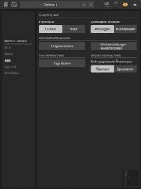
The Claravox App (Claravox Advanced Software Editor by Moog Music Inc. Version 1.0.4 build 53) has to be used to set the sound parameters. Even in TRADITIONAL mode, it is necessary to use this software application to modify parameters to get the instrument sound right. This means, that the CV-C theremin is only fully functional as long as there exist external devices running the application via USB connection. It is likely that the application gets updates only for a short period of time. This shows that the CV-C theremin must be regarded as a fully digital device, relying on external control by PC or other IT equipment.
It is not possible to set the parameters to achieve the true analog theremin-sound because important adjustment parameters are not provided (and the single-sine raw sound shape of the classical instruments designed by Leon Theremin is not generated). In fact, the CV-C theremin represents a Moog synthesizer which is raped to behave somewhat like a theremin. In addition, the fully digitally generated signals are modified using analog circuits. The fully digital generation of the raw waveform is of course not thoroughly stated within the user manual diagrams. Even the TRADITIONAL mode does not represent an analog theremin.
The pitch-frequency signal of the variable oscillator (located at the small pitch-oscillator board) is converted to a constant amplitude / duty-cycle square-wave by U26. It is then supplied to the digital mixer (U32) where the difference frequency of the variable oscillator signal to the 320kHz reference frequency-signal (sourced by the main DSP U8) is synthesized. The resulting audio-signal represents a triangle wave of constant amplitude and duty-cycle. The signal is additionally amplified by U17 where the upper triangle part is somewhat clipped. The shape is therefore somewhat similar to e.g. the EW theremin raw waveform, but the duty-cycle does not change with pitch sufficiently – the duty-cycle change is vital to the sound of a theremin. Switching between TRADITIONAL and MODERN mode connects the output of U17 (clipped triangle) or the D/A converted waveform of AF Oscillator 1. to the analog wave-shaper.
To drive the analog circuits like the LM13700 voltage controlled wave-shaper (Wave / Brightness) or the simple LM13700 voltage controlled low pass filter (Filter), a digital signal (Oscillator 1) is processed by the main control unit (DSP) and converted to an analog audio signal by one channel of a dual channel D/A converter. The other channel sources the signal of the so called digital Oscillator 2. All analog- and control signals are generated and processed digitally by the main control unit. The voltages controlling the following analog circuits for additional manipulation of the analog audio signals are generated by the main unit using pulse width modulation (PWM). Because all signals are digitally generated and processed anyway, it is very likely to convert the CV-C synthesizer to emulate the classical (tube based) instruments of C. Rockmore or even the RCA theremin perfectly using Oscillator 2 (because the waveform is not manipulated by the insufficient analog wave-shaper circuit of Oscillator 1). As mentioned before, this is only possible when the characteristics of these instruments are respected and digitally implemented by processing signals using the appropriate characteristic curves. This means that not the full-wave rectified sine like signal (as favored by R. Moog and used for the signal of Oscillator 1) has to be generated, but the single-sine pulse signal, already presented at aetherwellen-musik.de, which provides in fact two synced pulses, which differ in pulse-width. Only this signal, as generated by the instruments of LT (Leon Theremin), will give the full analog theremin sound.
To even come somewhat close to the behavior and sound of a theremin instrument, the digital control values for pitch and volume, derived from the antenna-sensors (formally known as control voltages Pitch-CV and Volume-CV), in the first place have to be used for influencing the pulse-width (Wave-Form) of the audio signal. The necessary characteristic curves for pitch- and volume control as already presented at aetherwellen-musik.de (EW-Modification) are not taken into account. These curves cannot be adjusted sufficiently using the CV-C theremin application as well.
")
Why is this not possible, even if there are somewhat hidden grey / blue arrow-icons to activate the adjusters for the amount of pitch- and volume control to influence the Wave-Form are provided? It is not transparent how the control parameters do affect the pulse-width (there is no curve shown, only percentage values are displayed) and it is not possible to separately adjust the required low, mid and high register. This means, only one of the registers will sound as desired, even when the provided digital control values for pitch and volume are used to control the behavior of the sound.
In a theremin as designed by LT (Leon Theremin), the sound behavior is inherent to the used circuits and components; this is why it is not necessary to apply control voltages to a real theremin. At the CV-C synthesizer, the applied circuits and derived signals do not provide the information to create a pleasing true analog theremin sound; that's why the sound has to be digitally emulated using complex characteristic curves. At the current state of the CV-C synthesizer, it is not possible to adjust the necessary curves. Of course, the firmware and application software could be updated with correctly implemented curves and the necessary user interface.
Nevertheless, the CV-C synthesizer, when adjusted as close as possible to the already provided typical characteristic curves using the existing simple adjusters can be made to sound much better. The sound should be at least of the quality achieved by the modified EW; refer to EW modifications.
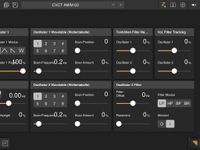
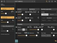
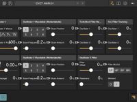
Some still experimental parameter files for the TRADITIONAL mode, which can be loaded to the Claravox App and stored to the timbre selection knob of the instrument, are given below:
CVCT AWM 01
CVCT AWM 02
CVCT AWM 03
All three Files are include in:
 | Claravox-APP-Parameter_AWM_01-03 Parameter files for the TRADITIONAL mode (Claravox App) Claravox-APP-Parameter_AWM_01-03.zip (2.51KB) |
Parameter files for the TRADITIONAL mode (Claravox App)
| Claravox-APP-Parameter_AWM_01-03.zip (2.51KB) |


Issues, Flaws and Improvements of the Moog
Claravox Centennial (CV-C) Theremin
 | ||||||
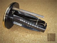
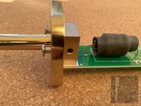
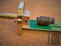
1. | Issue: | Loose contact of fully enamel varnish coated brass volume-antenna to antenna-jack’s contact spring, causing unstable operation or complete loss of volume control. | ||||
Solution: | Carefully apply tiny amounts of acetone liquid to the lower end of the antenna-shaft which fits the antenna-jack (approx. 25mm) to partially remove the coating. The solvent (acetone) can be applied using a soft cloth, wiping off the dissolved varnish coating. To prevent oxidation of the brass, the contact area has to be plated with a thin layer of e.g. tin. Ideally, this is done galvanically during production. It is even possible to add the tin layer subsequently using a 80W power soldering-iron. Note: This is not a optimal solution. Adding a thin tin layer just reduces the amount of corrosion as it would be the case with bare brass surface. Electrical contacts are usually made of a base of brass or bronze which is plated with a thin layer of noble metal. To achieve optimal electrical contact, the smooth antenna contact surface as well as the smooth contact spring surface inside the antenna mount plating has to apply e.g. hard gold, hard gold flashed palladium-nickel, platinum, (or e.g. alloys of gold, platinum, silver, palladium, nickel). Only a clean galvanization applying a thin layer of the low resistance materials as mentioned, which have been used for decades, ensure reliable electrical contacts. Chrome, which has usually used so far for plating e.g. the EW Theremin antennas, sufficiently prevents the metal base from corrosion as well but yields a higher contact resistance. | |||||
Pictures: | 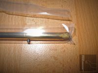 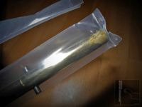 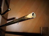 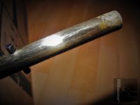 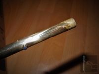 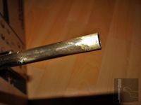 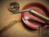 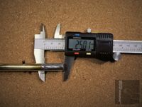 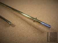 | |||||
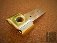
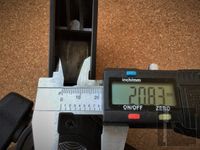
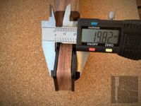
Factory Rework: | Jan. 2022: The replacement volume-antenna is reported to be much heavier than the old one (195 g), which is now determined to be 409 g; thus the weight has approximately doubled. It is unclear if the material has been altered and/or the construction changed from tubing to solid matter. Brass has a density of (8.1..8.7) g/cm3, copper 8.95 g/cm3 and (stainless) steel (7.7..8.2) g/cm3, this does not explain the increase in weight. Presumably, a material is used which is galvanically coated with brass. Apparently, the whole antenna has been coated but the contact area has not been masked during the galvanization process, which made it necessary to mechanically grind the contact area to remove the enamel and brass layer. As can be seen from the picture (kindly donated to aetherwellen-musik.de by the owner of instrument #00021), the contact area exhibits small corrugations, which will in the long run damage the coating of the antenna contact inside the antenna mount when to heavy. The corrugations will then act like a rasp, rasping down the plating of the contact spring. The damaged contact area will oxidize; therefore it is likely that the antenna has to be turned each time the instrument shall be played to remove the oxidation layer and restore the electrical contact. The author used acetone liquid to remove the enamel and added a plating of tin to prevent the oxidation of the brass at the original antennas. The tin layer is very soft, not damaging the plating of the contact springs. Adding the thin tin layer just reduces the amount of corrosion and oxidation as it would be the case with bare brass surface (see note above). | |||||
Factory Rework Picture: |  Theremin #00021 Factory Reworked Volume-Antenna 01-2022") | |||||
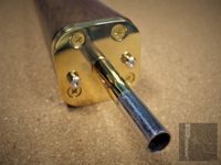 | ||||||
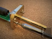
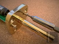
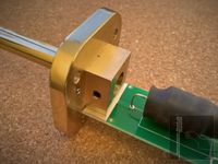
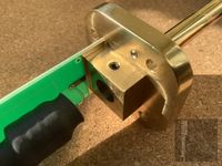
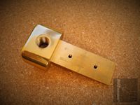
2. | Issue: | Loose contact of fully enamel varnish coated brass pitch-antenna-arm unit to antenna-jack’s contact spring, causing unstable operation or complete loss of pitch performance. | ||||
Solution: | Carefully apply tiny amounts of acetone liquid to the pitch antenna’s threads (antenna-rod and -arm) as well as to the lower end of the shaft which fits the antenna-jack (approx. 25mm) to partially remove the coating using e.g. cotton swabs. The dissolved varnish coating can be wiped off by a soft cloth. To prevent oxidation of the brass, the contact area has to be plated with a thin layer of e.g. tin. Ideally, this is done galvanically during production. It is even possible to add the tin layer subsequently using a 80W power soldering-iron. Note: This is not a optimal solution. Adding a thin tin layer just reduces the amount of corrosion as it would be the case with bare brass surface. Electrical contacts are usually made of a base of brass or bronze which is plated with a thin layer of noble metal. To achieve optimal electrical contact, the smooth antenna contact surface as well as the smooth contact spring surface inside the antenna mount plating has to apply e.g. hard gold, hard gold flashed palladium-nickel, platinum, (or e.g. alloys of gold, platinum, silver, palladium, nickel). Only a clean galvanization applying a thin layer of the low resistance materials as mentioned, which have been used for decades, ensure reliable electrical contacts. Chrome, which has usually used so far for plating e.g. the EW Theremin antennas, sufficiently prevents the metal base from corrosion as well but yields a higher contact resistance. | |||||
Pictures: |  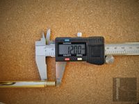 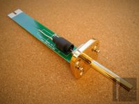 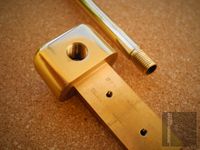 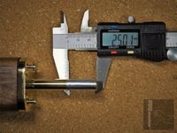 | |||||
Factory Rework: | Jan. 2022: The replacement pitch-antenna is reported to be much heavier than the old one (109 g), which is now determined to be 259 g; thus the weight has more than doubled. It is unclear if the material has been altered and/or the construction changed from tubing to solid matter. Brass has a density of (8.1..8.7) g/cm3, copper 8.95 g/cm3 and (stainless) steel (7.7..8.2) g/cm3, this does not explain the increase in weight. Presumably, a material is used which is galvanically coated with brass. Apparently, the attachment rod of the pitch-antenna- arm has been coated but the contact area has not been masked during the galvanization process, which made it necessary to mechanically grind the contact area to remove the enamel and brass layer. As can be seen from the picture (kindly donated to aetherwellen-musik.de by the owner of instrument #00021), the contact area exhibits small corrugations, which will in the long run damage the coating of the antenna contact inside the antenna mount when to heavy. The corrugations will then act like a rasp, rasping down the plating of the contact spring. The damaged contact area will oxidize; therefore it is likely that the pitch-antenna-arm has to be turned each time the instrument shall be played to remove the oxidation layer and restore the electrical contact. The author used acetone liquid to remove the enamel and added a plating of tin to prevent the oxidation of the brass at the original antennas. The tin layer is very soft, not damaging the plating of the contact springs. Adding the thin tin layer just reduces the amount of corrosion and oxidation as it would be the case with bare brass surface (see note above). | |||||
Factory Rework Picture: |  Theremin #00021 Factory Reworked Pitch-Antenna 01-2022") | |||||
 | ||||||
3. | Issue: | The enamel varnish of all coated brass surfaces, like the antennas, will get scratched easily (even by mounting the antennas to the Theremin body), which looks quite unaesthetic. The coating is extremely thin and lacks durability. | ||||
Solution: | Carefully wash off all varnish coating from the brass metal surfaces (e.g. antennas) using acetone solvent and protect them by a thin layer of appropriate acid-free conservation-wax, which can be renewed from time to time | |||||
Pictures: | 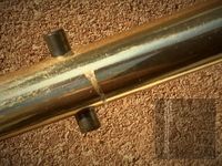 | |||||
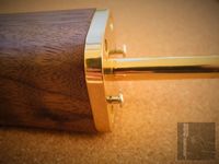 | ||||||
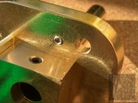
4. | Issue: | Loose pitch-antenna-arm locking screws. The two ‘internal hexagon’ locking screws are additionally tightened by counter-grub-screws from the inside of the antenna-arm compartment, but got loose when turning the arm during attach- and detachment anyway. | ||||
Solution: | The two screws have to be furnished with locking varnish at the inside thread before screwing them in, preventing them from future loosening. To tighten the small screws, at the pictures a 2mm 'bit with Allen/Torx profile' is used. It is advisable to use a 2mm 'Torx key with Hexagon profile', because of the applied 'internal hexagon' screws. | |||||
Pictures: | ||||||
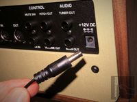 | ||||||
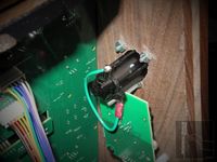
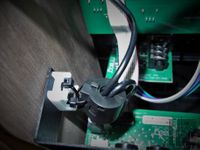
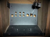
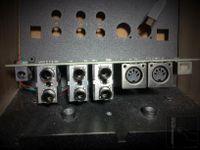
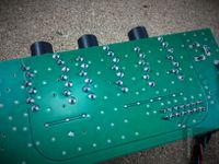
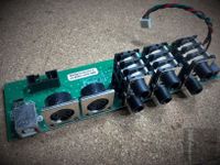
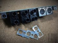
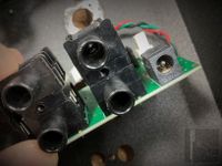
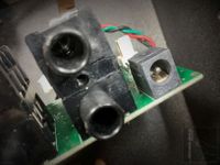
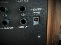
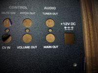
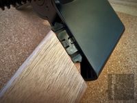
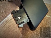
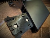
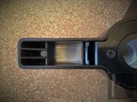
5. | Issue: | The 12V power connector is prone to fall of the back of the instrument because it is not secured and sits quite loosely. In addition, the connector has no real strain relieve because the applied connector’s plastic is way to hard and so the used two-wire cable is likely to break at the transition after some time of use. | ||||
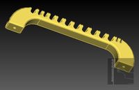
Solution: | Re-design of the rear-connector PCB (because there is no appropriate pin-compatible outer threaded sleeve jack available); replace simple DC barrel-type power jack and power-unit connector by versions with outer threaded sleeve that screw mates to the chassis mount jack outer thread, providing a secured connection. The connector of the power-unit also has to provide a soft strain relieve to protect the cable from getting shattered. As a temporary solution (or a general series remedy), a cable fixing bracket is proposed which not just only fixes the 12V power cable but also the other cables (especially the USB cable). It is attached to the CV-C Theremin using two of the four already provided screws which fix the rear cover to the connector panel. The cable fixing bracket shown in the pictures below was manufactured using a standard 3D (PLA) printer. It was painted to appear wooden like. | |||||
(02.08.2023) | Because of issue No.18 (Crackling Noises), the DC jack had to be replaced. This was done using special 3D printed insulation plates to hold a panel-mount jack with outer threaded sleeve (see pictures). In addition, the correct grounding (digital / analog) to the rear-panel metal-plate has been established. | |||||
Pictures: | ||||||
(02.08.2023) | ||||||
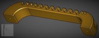
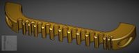
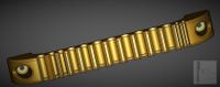
CAD: |
Claravox Cable Fixing Bracket CAD mesh file (.stl) for 3D printing the Claravox Theremin Cable Fixing Bracket
| |||||
Additional Calble-Fixing (CVC-CF) CAD files can be found in the Hardware section. | ||||||
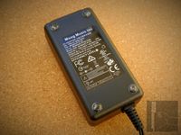 | ||||||
6. | Issue: | The 12V power-unit does not provide rubber-foots to hold it in place. Theremin instruments and connected parts and cables have to be kept as fixed to the intended position as possible, moving even accidentally, especially during a performance, has to be prevented under all circumstances. | ||||
Solution: | Add four small self-adhesive rubber foots to the lower side of the power-unit (those foots might be additionally fixed by appropriate glue). | |||||
Pictures: | 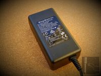 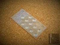 | |||||
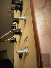 | ||||||
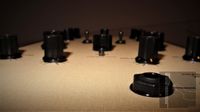
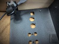
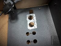
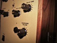
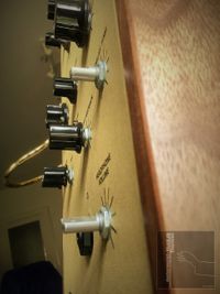
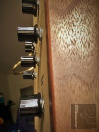
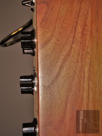
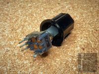
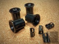
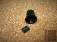
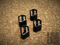
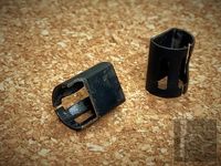
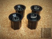
7. | Issue: | The small knobs are mounted to high above the front panel, compared to the knobs of bigger diameter, due to incompatibility of potentiometer shaft length and knob hole depth (refer to #19). | ||||
Solution: | Replace all the small incompatible knobs by adequate ones or replace the potentiometers with incompatible shaft by correct ones witch match the used knobs. A temporary solution is to carefully machine partially away about two to three millimeters of the knob’s metal clip-spring and of the torsion limiting boundary inside the knob’s hole, leading to approx. 2..3mm more insertion depth. | |||||
Factory Rework: | Holes have been partially been milled out and fillets have been partially removed at the back of the front-panel (see pictures). | |||||
Pictures: | ||||||
(02.08.2023) | 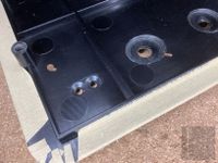 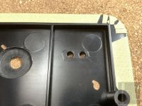 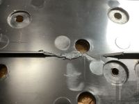 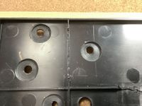 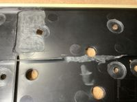 | |||||
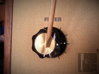 | ||||||
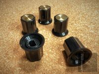
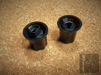
8. | Issue: | All knobs have a small brass like plate which is covered by a thin protection plastic film. This film has not been removed after production of the instrument was completed and makes the plate appear somewhat foggy. | ||||
Solution: | Carefully remove the protection plastic film from all knobs using e.g. a wooden toothpick. | |||||
Pictures: | 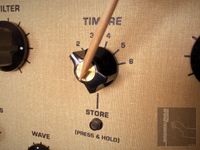 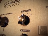  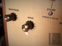 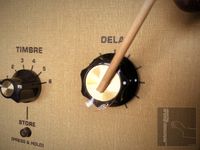 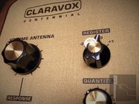 | |||||
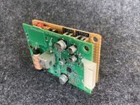
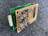
 CVCT_Vol-Osc-PCB_2WZ | ||||||
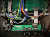
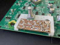
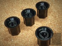
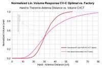
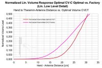
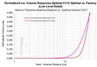
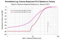
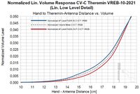
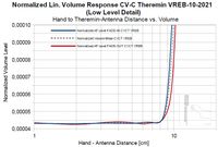
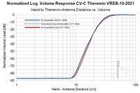
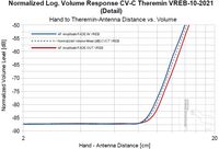
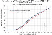
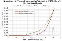
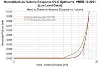
9. | Issue: | The volume response of the instrument is somewhat sluggish compared to e.g. the modified EW (REB); problematic at staccato playing (refer to 'Diagrams' below). There is no ‘Anschlagdynamik’ (over/undershoot of volume / acceleration of loudness level) noticeable, as already advised in the EW modification documentation. In addition, it seems that the audio signal cannot be reduced accordingly when playing at very low volume; the cut off distance can not be adjusted properly. The sensitivity and range of the volume-antenna is to low due to the long flexible cable which interconnects the antenna jack to the volume oscillator / antenna extension-coil board which is positioned to run close to the ground plane of the PCB (refer to 'Factory Condition Pictures' below). This leads to additional unstable capacity between the hot end of the extension coils and ground in parallel to the volume antenna. | ||||
(03.11.2023) | It is not correct as stated in the Moog 'Claravox Centennial User's Manual' (p. 34), that the volume of a theremin instrument will go to mute-level (the lowest possible volume) with the players hand inside (!) the volume-antenna-loop. This may only be the case with the Claravox Centennial Theremin (CVC-T). Staccato playing is therefore hindered, at least in 'Traditional' mode. The lowest volume is usually adjusted to be achieved with the hand about 8 centimeters away from the volume-antenna. The 'Etherwave Theremin User's Manual' (p.3) states that the Etherwave (EW) will reach mute level with the hand positioned 2 to 3inches (5 to 8 centimeters) away from the volume-antenna! | |||||
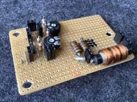
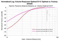
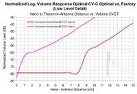
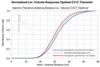
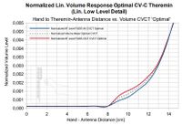
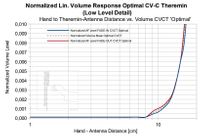
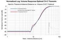
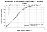
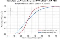
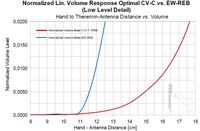
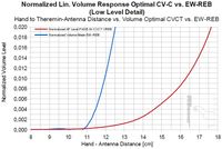
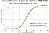
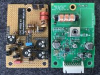
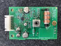
Solution: | Include volume-control improvements as already advised in the EW modification documentation according to the original designs of Leon Theremin – all is now included at the CVC-Theremin VREB-10-2021 (Volume Rockmorizer Extension-Board), refer to simulation, pictures and volume-response graphs below. A simple improvement can be achieved by the 'Optimal' configuration, described next: For the 'Optimal' configuration which corrects the factory installation, the long flexible cable which interconnects the antenna jack to the volume oscillator / antenna extension-coil board (refer to 'Factory Conditon Pictures' below) has to be re-positioned to run as far away as possible to the ground plane of the PCB. In addition, the cable can be tied up by e.g. a cable-tie to reduce its effective length and surface area (refer to 'Optimal Modification Pictures' below). This minimizes additional unstable capacity between the ‘hot’ end of the extension-coils and ground in parallel to the volume antenna, leading to higher volume antenna sensitivity. The volume-oscillator has to be re-adjusted when the cable position has been corrected. The same long interconnection cable is used at the pitch-antenna-arm jack, but has little effect because it is located at the ‘cold’ end of the pitch-antenna extension-coil which sits inside the pitch-antenna arm compartment. Note: The volume behavior can be somewhat improved by adjusting the VOLUME RESPONSE knob in MODERN mode without having to modify the hardware, but will not achieve the performance of the installed VREB. | |||||
(03.11.2023) | The improvement adjustments are performed as follows: A improvement which provides more flexibility in volume adjustment, can be achieved by adding the VREB-10-2021 (V1) board or the improved variants VREB V2 / V3 described at issue #22. | |||||
Factory Condition | 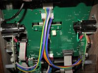 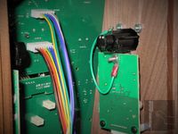 | |||||
Optimal Modification | 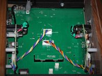 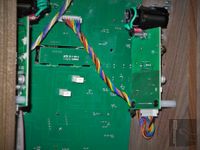 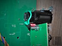 | |||||
Factory Rework: | Jan. 2022: The firmware (and hardware) was not altered regarding the volume response issues, as reported by the owner of instrument #00021; only a reset to the factory-settings had been noticed. | |||||
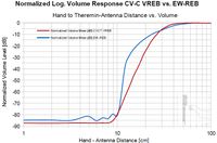
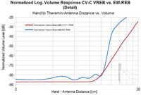
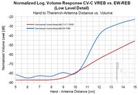
Factory/ Optimal Diagrams: | ||||||
CVC-T VREB-10-2021 | 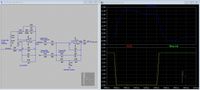 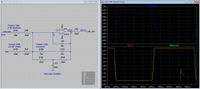 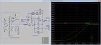 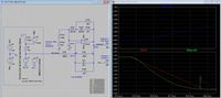 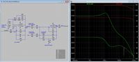 | |||||
CVC-T VREB-10-2021 Pictures: | 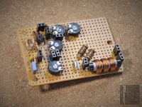 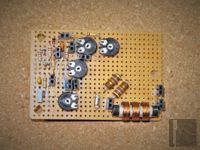 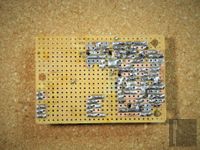 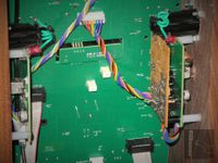 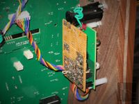 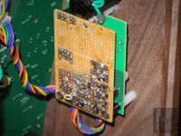 | |||||
CVC-T VREB-10-2021 Diagrams: | ||||||
| ||||||
10. | Issue: | When the position of the TIMBRE knob shall be changed, e.g. in TRADITIONAL mode from position ‘1’ to ‘2’-’6’, the firmware concept dictates to store the actually adjusted values before changing the TIMBRE knob position by pressing and holding the STORE button. If the values have not been stored, they are lost, because when resetting the TIMBRE knob to position ‘1’, the originally adjusted values, even when the knob positions of e.g. BRIGHTNESS and WAVEFORM have been left unchanged in the meantime, are not recovered. The actual knob values are overwritten by the stored values of TIMBRE ‘1’, the actual knob settings - the shown values of the knobs - are not the values which represent the recovered values and knob settings! A strange behavior can be noted when a timbre has been selected by the dedicated knob and e.g. the WAVEFORM knob is turned sightly – the timbre jumps from the actual recovered setting to the actually adjusted value. | ||||
Solution: | Firmware-Update; change operational concept of Claravox Centennial Theremin. The ‘1’ position of the TIMBRE knob shall be reserved for the ‘real-time’ adjustments at the knobs, this means each time timbre ‘1’ is selected, the set values actually defined by the positions of all control knobs are in effect. For storing the found values to the remaining five TIMBRE knob positions ‘2’-’6’, the STORE button shall be pressed and the switch position has to be changed to the one where the new timbre shall be stored. The switch position has to be selected during the STORE button ‘blinking three times’ period. The measures do not change the behavior for TIMBRE knob positions ‘2’-’6’, to be able to sort of modify stored values. Only position ‘1’ is exclusively reserved for the actual knob settings and cannot be used for storage. This prevents the values to jump from the stored to the actual set ones when slightly turning a knob by switching the TIMBRE knob to position ‘1’ first. Now one can switch between timbres (even the actually adjusted) without the need of saving, which makes the handling of the instrument much more comfortable. | |||||
 | ||||||
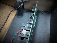
11. | Issue: | Slack cabling, especially the USB cable and its EMI ferrite is not appropriately tightened; two connected cable-ties have been used. At the top USB jack, no additional fixing is existent. The harnesses of cables near the antennas, connecting the antenna-oscillator boards, are quite lengthy and can change their positions because they are not fixed or tightened anywhere. This may cause changed antenna calibration after vibrations due to transportation. | ||||
Solution: | Directly fix the EMI ferrite of the USB cable by directly connecting the provided lugs of the ferrite-core housing and the mounting bracket at the theremin chassis using a single appropriate cable-tie. The ferrite shall not move when shaken. The upper end of the USB-cable can be fixed in place by feeding it through a suitable fastening-eye or using a similar fixing solution as already applied for the EMI ferrite-core. | |||||
Factory Condition Pictures:
| 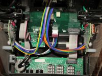  | |||||
Modification Pictures: | 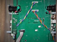 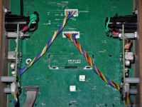 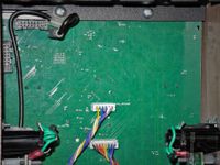 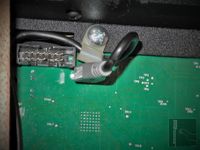 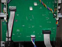 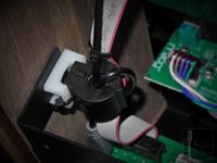 | |||||
|
12. | Issue: | Peak volume of MODERN mode is much louder than of TRADITIONAL mode. | ||||
Solution: | Rise amplification factor of 'TRADITIONAL' mode by changing hardware, or change volume of 'MODERN' mode by lowering VCA analog control digital DAC output amplitude (firmware-update) to match 'TRADITIONAL' mode when switching between modes; refer to issue #22. | |||||
| ||||||
13. | Issue: | The CV-C Theremin produces a loud pop noise (at the Main Output), especially when switched off. | ||||
Solution: | Implement a hardware switch-off pop-noise muting circuit, e.g by using a simple relay which delayed connects the audio jacks at power on and immediately disconnects the jacks at power off (before the supply voltage has fallen to much, producing the pop noise); partial hardware re-design. | |||||
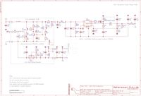
(02.08.2023) | A appropriate circuit was developed which suppresses the switch-on/off pop-noise sufficiently. In addition, a low-power stereo amplifier was added to drive headphones (or small high efficiency speakers) directly by the specially generated speaker-simulation signal. This stereo-signal reassembles the sound experience the player has when playing at a real speaker set-up but only wearing headphones and not connecting an external speaker. This is especially useful to not disturb the neighbors. Refer to the schematic and pictures below. | |||||
Modification Schematic:(02.08.2023) | ||||||
CVC-T Theremin Ambient Processor / Audio-PA / Muting Schematic CVC-T Theremin Ambient Processor / Audio-PA / Muting Schematic
| ||||||
Modification Pictures: | 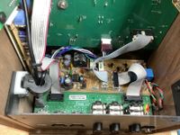 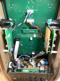 | |||||
Measurements: | 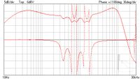 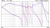 | |||||
Sound-File: |
CVC-T Theremin Ambient Processor Audio Stereo-signal reassembles sound experience playing at real speaker set-up wearing headphones
| |||||
 | ||||||
14. | Issue: | The CV-C Theremin produces squeak noises when the volume is close to cut-off (mute) while the hand is very close to the volume antenna shortly touching it while wiggling. | ||||
Description:
| It was assumed, that this behavior is possibly caused by the very small capacitor value (220pF) of the SMD capacitor located at the Volume-Oscillator board, connected in series to the volume-antenna and extension coil L15 (5mH), providing DC decoupling and high-pass filtering to reduce mains low frequency modulation interference. When to small, the capacitor effectively will serve as ‘shortening capacitor’ to the antenna extension-coil, reducing its value. This may lead to frequency jumps to unintended values when touching the volume-antenna, causing the derived volume-control voltage to jump, too. Frequency jumps of the antenna resonator- and oscillator circuits (of both - volume or pitch circuits) have to be prevented under all circumstances because e.g. the oscillators might get locked to this wrong frequency. When locked, usually the antenna has to be touched or the supply voltage has to be interrupted to get the oscillator back to its intended frequency. The locking may even appear when switching on a theremin (especially with high antenna sensitivity meaning wide pitch- and volume-range), e.g. when grounding conditions have changed extremely, probably because the location of the instrument has been changed. Frequency jumps as described above cannot appear this way at the CV-C Theremin volume-control due to the application of the volume oscillator- and antenna-resonator detector designed by R. Moog and already applied e.g. at the EW-S/+ Theremin. This circuit does not use the small-bandwidth (oscillator frequency deviation < 5kHz) configuration as originally developed by L. Theremin and used in the Rockmore/Rosen Theremin instruments. The circuit located at the volume-oscillator board of the CV-C Theremin relies on a wide frequency deviation of the antenna resonator (antenna and extension coil) from approx. 510kHz to < 320kHz. The highest resonance frequency of the antenna resonator occurs when the hand is far away from the volume-antenna. When the hand is very close, slightly touching the enamel covered brass volume-antenna loop, approx. 320kHz is reached. Unfortunately, this frequency is equivalent to the frequency of the CV-C Theremin’s pitch oscillator! The pitch control hand and the body of the player pick up the high-frequency signal of the pitch-oscillator as transmitted by the pitch antenna resonator and conduct it to the hand near the volume antenna. When this hand comes close to the volume-antenna, the volume resonator lowers its frequency until at some point very close, it resonates at the typical 320kHz pitch oscillator frequency which is now converted to a noticeable control voltage leading to a sharp rise in volume, even when normally close to cut-off. Because the volume-antenna is varnished, the hand does not make direct electrical contact to it which would effectively ground it which is the case e.g. at the EW-S/+ Theremin. The grounding would prevent lots of pitch oscillator RF from penetrating the volume resonator/detector circuit; thus the volume-control would behave normal (very low volume when hand close to antenna, no sudden jumps in level of sound). This can also be observed when the player is specially grounded to earth (PE). | |||||
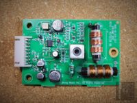
Solution: | Insert Wave Blocker device to prevent pitch-oscillator signal (320kHz) from entering the volume-antenna resonator, which can resonate at 320kHz when hand is very close to the antenna. It consists of a additional parallel resonator circuit (1.1mH / 220pF) connected in series to the cold end of the volume-antenna resonator extension coil (L15). Because the volume control circuit of the CV-C Theremin is extremely sensitive to deviations of mechanical and electrical tolerances, inserting the proposed Wave Blocker is likely to change the cut-off position of the hand near the volume-antenna. It was noticed that complete cut-off did not occur and was not adjustable at the volume-oscillator tank or the volume control-voltage amplitude defining trimmer R57, located at the volume-oscillator board. A somewhat similar behavior had been already noticed at the general volume-control issue 9. which was caused by the additional parallel capacity to the volume-antenna (slovenly cable positioning). To overcome all this, a dedicated piggy-back board (CV-C Theremin VREB-10-2021) was designed to minimize the additional stray capacitance, provide at least trimmers for cut-off (R59) and control-voltage amplitude (R57), hold the antenna extension-coil (L15) and the 320kHz blocking parallel-resonator (2x 470uH / 220pF). The overall coil inductance of the parallel-resonator can be adjusted by bending the coils changing the distance to each other. The CV-C Theremin will now (probably for the first time) work correctly applying the Wave-Blocker, when volume-oscillator tank, volume control-voltage amplitude trimmer R57 and especially the cut-off trimmer R59, which has a big influence on the low-level volume response, are adjusted correctly. | |||||
Pictures: | 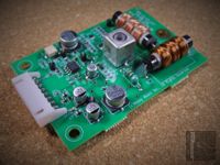 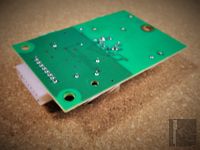 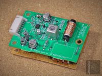 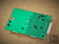 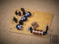 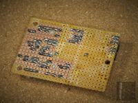 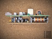 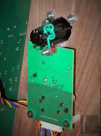 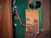 | |||||
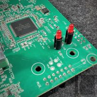 | ||||||
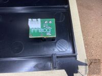
15. | Issue: | Main PCB deformed by wrong LED spacers 15. (refer to #19). | ||||
Description: | The distance of the Midi- and Mute-LED from main PCB to front-panel as defined by the LED spacers is approx. 2mm to large causing the circuit-board to be bend when screwed tightly by the nuts of the potentiometers. Deformation of printed circuit boards may lead to cracks of tracks and solder joints. | |||||
Solution: | Replace LEDs and spacer by parts with appropriate length or at least cut off 2..3mm from the spacer (as shown in the pictures below). | |||||
Pictures: | 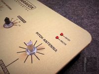 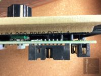 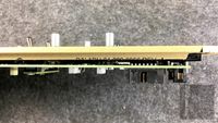 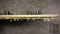 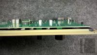 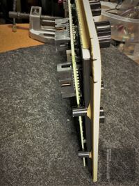 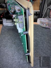 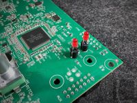 | |||||
 | ||||||
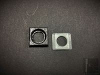
16. | Issue: | Faulty design of special antenna connector-jack (contact-spring blocks antenna from being inserted) | ||||
Factory Rework: | A standard cable-tie was added during production to position the contact-spring correctly. | |||||
Solution: | Remove cable-tie, drill two 0.8mm holes to hold corresponding solid wire which durable positions the contact-spring correctly (see pictures). | |||||
Pictures: | 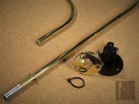 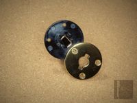 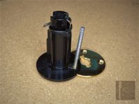 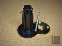 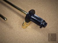 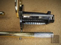 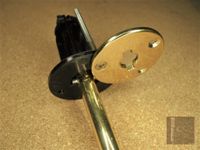 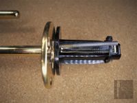 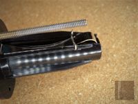 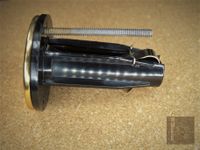 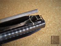 | |||||
 | ||||||
17. | Issue: | Current of power-indicator LED to high (probably matched to +5V but driven by +12V), leading to excessive heating of LED and series-resistor. | ||||
Solution: | Replace wrong 220R resistor by correct one with value of at least 470R. | |||||
Pictures: | 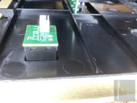 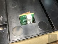 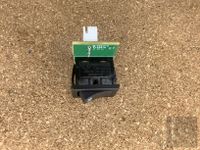  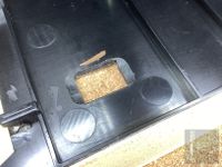 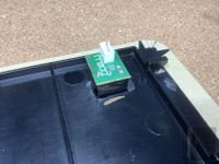 | |||||
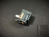 | ||||||
18. | Issue: | Crackling noises when touching/turning 12V DC connector due to excessive oxidation of the low-grade contact-material at the power-jack. The oxidization process was likely facilitated by the outgassing of the varnished wooden housing. | ||||
Solution: | Replace 12V DC connector (refer to issue No.5). | |||||
Pictures: | 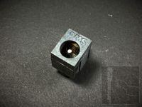 | |||||
|
19. | Issue: | Wrong mechanical design of front-panel (plate thickness dimension to large), causing issues #7 and 15#. | ||||
Solution: | Redesign of front-panel plate, replacement. | |||||
Pictures: | | |||||
 | ||||||
20. | Issue: | Faulty design of -10V voltage converter, getting damaged when overloaded. | ||||
Description: | The applied high-power DC-DC converter (RT8279) can provide much more output current (up to 5A) than needed for the -10V rail (typ. 150mA). The used component values are therefore low power parts (especially the converter choke), chosen for only small currents. When over-current conditions occur, these components overheat and get damaged permanently because the RT8279 still delivers its internally set maximum peak current (up to 7.5A) until it gets overheated itself, causing the chip to shut off undamaged. | |||||
Solution: | Add fuse at least at the input of the -10V converter to prevent it from overheating and damaging components when output over-currents occur (HW redesign). | |||||
Schematic: | ||||||
CVC-T -10V Converter Extension Schematic CVC-T -10V Converter Extension Schematic
| ||||||
Pictures: | 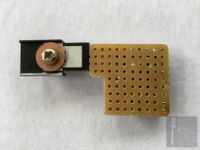 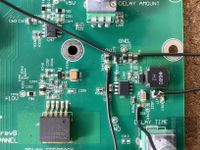 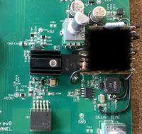 | |||||
 | ||||||
21. | Issue: | Insufficient function of analog low-pass filter (LPF; 'FILTER' knob), providing no ringing and therefore no formant effects (Traditional Mode). It must be noted that the knob 'WAVE' already performs a LPF function because it sets the slope rise- and fall time of the square limited audio signal. | ||||
Solution: | Add hardware modification (refer to schematic 'CVC Simple Formant Filter - CVC-SFF' and pictures). This changes the already existing two voltage-controlled low-pass filters (LM13700) to resonate and provide two slight format peaks when 'FILTER' knob turned fully clockwise. When using other hardware component values, the formant effect can be increased – leading to strong voice-like formants. | |||||
Schematic: | ||||||
CVC-T Simple Formant Filter Schematic CVC-T Simple Formant Filter Schematic
| ||||||
Pictures: | 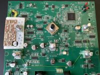 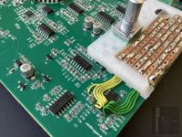 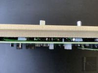 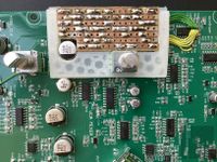 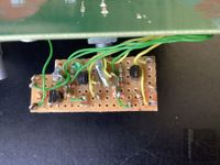 | |||||
 | ||||||
22. | Issue: | Volume cannot reach mute level (level which is equal to 'MAIN OUTPUT' switch set to 'MUTE' position; no signal noticeable) at lowest hand position close to / inside volume-loop-antenna at 'TRADITIONAL' mode. | ||||
Description: | It was reported by several users of the CV-C Theremin (aka Claravox Centennial Theremin), that there persists an issue in 'TRADITIONAL' mode of mute level (level which is equal to 'MAIN OUTPUT' switch set to 'MUTE' position; no signal noticeable) is not reached at lowest hand position close to or with hand already inside the volume-loop-antenna, even at higher serial numbers. | |||||
There is a draft proposal (9. Issue: Volume Response) already published at aetherwellen-musik.de in 2021 (CVC-T VREB 10-2021), which mainly corrects for volume control-voltage level curve and offset (including blocking pitch oscillator frequency and reducing antenna-jack cabling length for improved sensitivity). The additional parts are located at a piggy-back board which is mounted to the back of the volume-oscillator board, close to the volume antenna-loop connector. In combination with the volume-oscillator's variable coil (L19), the control voltage can be adjusted by trimmers (amplitude and offset) for optimal volume-control range, including cut-off approx. 5 to 8 centimeters above the volume-loop antenna. | ||||||
Because a possible modification of the main-board is quite complicated and risky, two new versions of the volume-extension board (CVC-T VREB 10-2021) have been eveloped, denoted as CVC VREB V2 and CVC VREB V3. The changes affect TRADITIONAL and MODERN mode; MODERN mode provides means to digitally adjust the response curve, so this is not significant. All has kept as simple as possible, nevertheless providing noticeable improvements. It must be noted that even when improvements are obviously recognizable, the proposed circuit changes can only be seen as makeshifts. | ||||||
Note: | ||||||
Because the issue still persists with higher serial numbers, it was necessary to dig deeper into the functionality of the main-board (front-panel board), which contains the DSP processor (U8). This DSP controls all functions, even at 'TRADITIONAL' mode. Therefore it is extremely important that the firmware works correctly in both modes. | ||||||
The volume-detector output-signal (approx. 0V to +3.3V), which reflects the hand position of the player above the volume antenna, enters the main-board at connector J7-1. It is then separated in two paths; one straight for 'MODERN' mode (denoted as 1. 'VOL_OSC_ADC'; TP56), the other complicated one for 'TRADIDIONAL' mode (denoted as 2. 'VOL_VOLT'; TP26). | ||||||
1. 'MODERN' mode 'VOL_OSC_ADC' volume-control signal path | ||||||
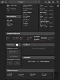
Using the 'Claravox' app set to 'Diagnostic Mode' (only functional for Apple iOS), e.g. the DSP-ADC values can be monitored, see pictures below. | ||||||
 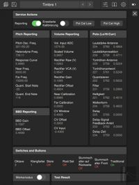  | ||||||
An indicated value for 'Vol. Input ADC' of typ. 4000 (equal to 'Scaled Volume' value 1.0000 and value 'Rectifier Raw' (V): 3.3000) represents the minimum ('MUTE') audio-signal level. A indicated value for 'Vol. Input ADC' of typ. 0000 (equal to 'Scaled Volume' value 0.0000 and value 'Rectifier Raw' (V): 0.0000) represents the maximum (!) audio-signal level. The A/D converted values (representing the hand position near the volume antenna) are digitally processed by the DSP according to the volume antenna calibration (near, far) and the setting of the volume-antenna 'RESPONSE' knob. The volume-antenna calibration values are also displayed at the 'Claravox' app 'Diagnostic Mode' denoted as 'Near Calibration' and 'Far Calibration'. The digitally processed volume-control values are D/A converted and routed via DSP controlled analog-signal switch (U21), which allows for digitally selecting between the main VCA analog control voltage for 'TRADITIONAL' or 'MODERN' mode, to the main audio signal exponential VCA (U18C). | ||||||
(13.10.2023) | The audio-signals of MODERN mode are the D/A converted waveform of Oscillator 1. (additionally processed by analog wave-shaper and filter) and Oscillator 2. (no additional analog processing). The audio-signal of TRADITIONAL mode is the waveform of the digital mixer U32. To digitally select between Oscillator 1. (MODERN mode) and U32 (TRADITIONAL mode) signal, analog switch U4 is placed at the input of the analog wave-shaper. The analog processed signal of Oscillator 1. (or U32) is lead to VCA U18B and the signal of Oscillator 2. is lead to VCA U18A to allow for digitally selecting which signal is routed to the main volume-control VCA U18C - in addition, both signals can be mixed. The pre-selection VCAs only perform switching action, they are not intended for volume control. The applied exponential VCA has a used control range of -100dB (full attenuation at typ. +3V) to 0dB (unity gain at typ. 0V). There is the possibility of up to +20dB amplification when the control voltage is lowered down to typ. -0.6V. The used VCA has a exponential attenuation curve (at the EW theremin, the VCA has a linear control curve), which has (as we all know from the infection curves of the pandemic) a very slow rise at the beginning and a broad transition to the steep rising part. This bare exponential curve (e^x) is therefore unsuitable for theremin use; it makes it impossible to articulate staccato notes properly. There has to be a curve with sharper transition to the steep rising part, e.g. e^2x, which is possible by connecting two exponential VCAs in series - a hardware solution. Because the CV-C theremin is already fully digital controlled, the volume-control voltage, steering the main VCA, can be set to be processed for a sharper transition curve, depending on the setting of the 'RESPONSE' knob. 2. 'TRADITIONAL' mode 'VOL_VOLT' volume-control The following inverting-adder stage (U28A) provides unity gain for the voltage delivered by the VCA in combination with U22C and a additional voltage for offset-control, sourced via offset-amplifier U11D from D/A converter U12C. The D/A converter can only deliver positive output voltages; U11D is used to add an amount of a +5V reference voltage to shift the D/A output-signal. The offset-control signal now ranges from negative to positive values, even if the D/A converter sources only positive voltages. The output of the inverting-adder stage (U28A) with correctly set input voltages, ranges from 0V to +3.3V; it can be measured at TP26 (accessible at the bottom side of the main-board). The control voltage is then supplied to the corresponding DSP's A/D converter and via DSP controlled analog-signal switch U21 (which allows for digitally selecting between the analog control voltage of 'TRADITIONAL' or 'MODERN' mode) to the main VCA. | |||||
(13.10.2023) | The audio-signal of TRADITIONAL mode is the waveform of the digital mixer U32, which is routed via analog switch U4 (to digitally select between Oscillator 1 – MODERN and U32 - TRADITIONAL signals), to the analog wave-shaper and filter. After analog processing, the signal is lead to VCA U18B. The signal of Oscillator 2. (MODERN mode) is lead to VCA U18A to allow for digitally selecting which signal is routed to the main volume-control VCA U18C - in addition, both signals can be mixed. The pre-selection VCAs only perform switching action, they are not intended for volume control; at TRADITIONAL mode, the signal of Oscillator 2. is disabled at VCA U18A. | |||||
Using the 'Claravox' app set to 'Diagnostic Mode', the DSP-ADC values can be monitored. The A/D converted values (representing the hand position near the volume antenna) are not digitally processed by the DSP according to the volume antenna calibration (near, far) or the setting of the volume-antenna 'RESPONSE' knob in 'TRADITIONAL' mode. The volume-antenna calibration values can be set regardless of the instrument setting ('TRADITIONAL' or 'MODERN'). | ||||||
From the switch (U21) output, the volume-control signal reaches the main audio signal exponential VCA (U18C). As described before, the applied exponential VCA has a used control range of -100dB (full attenuation at typ. +3V) to 0dB (unity gain at typ. 0V). The used VCA has a exponential attenuation curve, which has a very slow rise at the beginning and a broad transition to the steep rising part. This bare exponential curve (e^x) is therefore unsuitable for theremin use; it makes it impossible to articulate staccato notes properly. As mentioned already, there has to be a curve with sharper transition to the steep rising part (e.g. e^2x). At the 'TRADITIONAL' mode, it is not possible to vary the steepness of the VCA control curve, because the main exponential VCA is directly controlled by the output signal sourced from U28A via the switch U21. Because of this direct control, it is absolutely vital to set the factors (D/A control voltages) for damping and offset of the 'TRADITIONAL' chain correctly, to achieve the desired volume-antenna control range form mute-level (cut-off) to full volume, even when imperfect in terms of steepness. | ||||||
Using the 'Claravox' app set to 'Diagnostic Mode', the DSP-ADC and DAC values as well as calibration constants can be monitored. It is not possible to set the constants (D/A control voltages) for damping and offset of the 'TRADITIONAL' chain manually! These are likely to be set during commissioning at the factory once (or are fixed and linked to the firmware). This means if something went wrong (e.g. cut-off / mute level adjustment for 'TRADITIONAL' mode), it is not possible to correct it by the user, simply adjusting the values accordingly. | ||||||
Additional notes about the applied volume control concept are given next, explaining the deficiencies of the fixed volume-oscillator, driving the antenna-extension-coil which serves directly as volume-detector resonator for the attached rectifier circuit. The circuit concept applied at the CV-C theremin for deriving a control-voltage which reflects the positions of the hand near the volume-control antenna-loop is quite similar to the one as used by R. MOOG at the EW theremin. It applies a fixed RF oscillator whose frequency does not change even when the loading of the attached antenna-resonator varies with additional capacity of the hand near the antenna. Only this resonator, consisting of the antenna and the attached extension-coil, produces voltage-changes according to it's momentarily (hand position dependent) resonance-frequency, which are rectified and filtered to get an analogous control-voltage. This concept is much less sensitive than the original circuit used by L. Theremin (LT) at e.g. the Rockmore theremin instrument (General Functionality of the Rockmore- and Rosen Tube-Theremin Instruments), which applies a frequency pulled variable volume-control RF oscillator with attached antenna and extension coil. This scheme, similar to the pitch circuit, provides a frequency-modulated (FM) RF signal. The signal is then supplied to a special detector-resonator of small bandwidth and fixed resonance-frequency, converting it to an AM modulated signal (the frequency stays unaltered). The now varying amplitude (amplitude modulation; AM), according to the frequency changes, is then rectified and filtered, producing the volume-control voltage. The simplified circuit devised by R. Moog relies on the wide bandwidth and large frequency changes of the antenna-resonator itself; the derived control voltage has to be additionally processed because there is no inherent appropriate curve adjustable for min./max. volume and cut-off. The circuit by L. Theremin uses only small bandwidths at the antenna-resonator, the detector-resonator and the volume-oscillator. There is no need to additionally process the derived control voltage because there is a inherent appropriate curve, adjustable for min./max. volume and cut-off, originating from the slightly different frequencies of the antenna-resonator, the detector-resonator and the volume-oscillator. The hardware-circuits which provide processing a appropriate volume-response curve vital for a theremin and important for 'TRADITIONAL' mode, are completely omitted at the CV-C theremin instrument. A usable curve is processed digitally by setting the antenna 'RESPONSE' knob accordingly at 'MODERN' mode only. The exponential curve provided by the applied VCA alone is not sufficient. Measures to process a improved response curve even at 'TRADITIONAL' mode are included in the circuit proposal of issue 9. (Volume Response). | ||||||
Solution: | The firmware has to be changed to provide the correct fixed values for damping and offset of the 'TRADITIONAL' chain. Probably, the factory commissioning has to be improved. The 'Claravox' app could be improved to make setting DSP-DAC values manually possible (at least those influencing the 'TRADITIONAL' chain) when in 'Diagnostic Mode'. To compensate for a probably insufficient factory calibration in 'TRADITIONAL' mode, the volume-extension board (CVC-T VREB 10-2021) was developed already in 2021. Updated versions are described below, denoted as CVC VREB V2 and CVC VREB V3. Those may be added to the volume-oscillator board to conveniently adjust for an improved volume-response curve, usually without having to change the main-board (front-panel board). A simple imperfect interim-fix is to (temporarily) shorten resistor R104 (located at the main-board) which is part of the voltage divider at U12 / U11C, which sets the level of the analog voltage used to control the main VCA (U18C) via damping of VCA U18D. By the short, which causes no harm to D/A converter U12 due to a large (10k) output series resistor, VCA U18D is set to unity gain, meaning no damping and leading to a higher control level of adequately amplitude for the main VCA at 'MUTE' level (typ. +3V). Probably, the control range of U11C and thus of the D/A converter U12D has to be expanded by applying the circuit similar to offset-amplifier U11D for D/A converter U12C, providing control down to negative voltages (e.g. -0.3V to +1V) for amplifying the volume-control voltage amplitude (and not just damping it). To completely disable the software-calibration for the 'TRADITIONAL' mode, set during commissioning at the factory, resistor R104 (DAMPING; located near U11) has to be shortened and R219 (OFFSET; located near TP26) has to be disconnected. Both resistors are located at the main-board (front-panel board). This measure may be necessary if the adjustment-range of the trimmer VR1 (located at the volume-oscillator board) and of the additional trimmers at the CVC VREB boards, in combination with volume-oscillator coil L19, is not sufficient to create a useful volume-control range. | |||||
Pictures: | ||||||
 | ||||||
Description: | Description of CVC VREB V2 | |||||
The control range is not sufficient to adjust for optimal volume control-range and cut-off. Because the range is not adequate, the trimmer is usually set to a stop at the factory. To make the fundamental adjustments possible, VR154 (offset) and VR150 (max. volume) have been added to the extension board. The wave blocker (jumper J1 not connected) can be externally adjusted using RF generator and oscilloscope by bending the coils L151/L152 closer to each other until maximum suppression is reached at approximate 320kHz. Depending on the jumper settings, the trimmers VR150 and VR154 have to be set to mid position (as well as the 'PITCH' knob), first. Then the volume oscillator coil (L19), located at the volume-oscillator board, has to be adjusted to get a basic volume response. | ||||||
(11.11.2023) | To get optimal response, both trimmers as well as the oscillator coil have to be adjusted alternately because the adjustments influence each other. During adjustment, the voltage at least at TP5 (approx. +3.3V @ min. volume / -0.3V @ max. volume) has to be observed. Track break TB150 at the volume-oscillator board was only necessary in the first version (CVC-T VREB 10-2021), it is not necessary at version V2 or V3. Track-break TB151 disconnects TP1 from the detector output. TP1 now has to be connected to U7B PIN6 via R151 (0R) to make it possible to establish the connection ‘B’ to the extension-board. The antenna extension-coil (L15) which is originally located at the volume-oscillator board has to moved to the VREB PCB, now denoted L150. | |||||
1. 'Standard' providing a response curve close to the optimal configuration of (CVC-T VREB 10-2021) | ||||||
2. 'Extended volume' providing a extended response curve | ||||||
3. 'Clean extended volume' providing a extended response curve including suppression of pitch RF (320kHz), solving the squeak noises issue #14 | ||||||
Composition and assembly of the CVC VREB V2 are shown at the pictures below. | ||||||
Schematic: |  | |||||
(11.11.2023) |
| |||||
Replaced by revision 0v2
| ||||||
Pictures: | 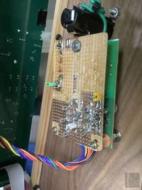 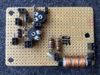 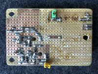 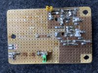 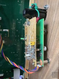 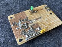 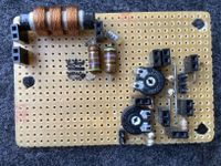 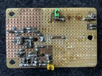 | |||||
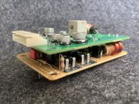 | ||||||
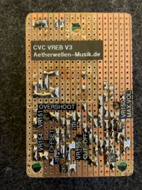
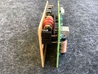
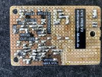
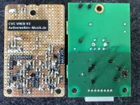
Description: | Description of CVC VREB V3 The circuit consists of the standard volume-control voltage detector (around D9) as developed by R. Moog (e.g. applied at the EW-Theremin), followed by inverting non-linear LPF amplifier (actually a non-linear current to voltage converter) around U7B and inverting-adder LPF amplifier U7A. Non-linearity, to compress the low-volume contol range to get a steeper response curve, is introduced by diodes D144/D145 at the feedback-path of U7B. Overshoot of the volume-control voltage is introduced by the included resonator, formed by the Bridged-T-Network at the feed-back path of U7A (velocity dependent volume response). The wave blocker ('Sperrkreis') composed of C150 and L151/L152 removes the pitch-oscillator's RF, injected to the volume-antenna. It is connected in series to the volume-antenna resonator. At the original circuit, only the single trimmer VR1 is provided which influences offset and amplitude of the volume-control voltage at once. The control range is not sufficient to adjust for optimal volume control-range and cut-off. Because the range is not adequate, the trimmer is usually set to a stop at the factory. To make the fundamental adjustments possible, VR154 (offset), VR150 (max. volume) and VR155 (cut-off) have been added to the extension board. The wave blocker can be externally adjusted using RF generator and oscilloscope by bending the coils L151/L152 closer to each other until maximum suppression is reached at approximate 320kHz. To adjust the circuit, the trimmers have to be set to mid position (as well as the 'PITCH' knob), first. Then the volume oscillator coil (L19), located at the volume-oscillator board, has to be adjusted to get a basic volume response. If this is not possible, VR155 has to be adjusted together with L19. To get optimal response, trimmers VR150, VR154 and VR155 as well as the oscillator coil L19 have to be adjusted alternately because the adjustments influence each other. During adjustment, the voltage at TP7 (approx. -0.3V @ min. volume / +0.7V @ max. volume) and TP5 (approx. +3.3V @ min. volume / -0.3V @ max. volume) has to be observed. Trimmer VR151 (overshoot) has only little effect at very fast volume changes (velocity dependent volume response) and is adjusted lastly. Track break TB150 at the volume-oscillator board was only necessary in the first version (CVC-T VREB 10-2021), it is not necessary at version V2 or V3. Track-break TB151 disconnects TP1 from the detector output. TP1 now has to be connected to U7B PIN6 via R151 (0R) to make it possible to establish the connection ‘B’ to the extension-board. The antenna extension-coil (L15) which is originally located at the volume-oscillator board has to moved to the VREB PCB, now denoted L150. Composition and assembly of the CVC VREB V3 are shown at the pictures below. | |||||
Schematic: |  | |||||
(11.11.2023) |
| |||||
Replaced by revision 0v2
| ||||||
Pictures: | ||||||
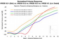 | ||||||
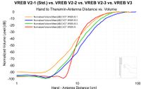
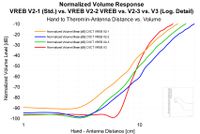
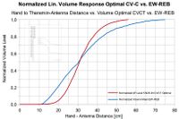
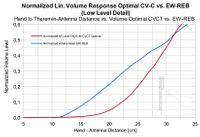
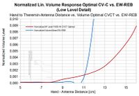
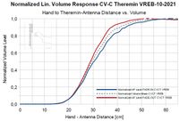
Diagrams: | Volume Response Curves of CVC VREB V2 and V3 In contrast to the volume-response curves previously shown for CVC-T VREB 10-2021, it was necessary to improve the resolution of the measurement to match the extended volume control range. The ZOOM H5 recorder and the Adobe Audition spectrum analyzer (digital FFT fundamental amplitude measurement) was used at 96kHz/24bit. To get the distance indication, the already described 'Theremin Hand to Antenna Distance Indicator Device' (THADID) was used. | |||||
 | ||||||
 | ||||||
|


")

")

Isues, Flaws and Improvements of the Moog Claravox Stand
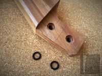 | ||
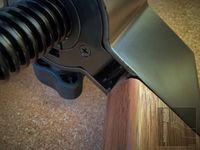
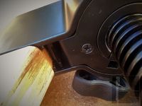
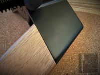
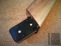
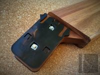
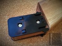
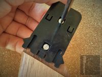
1. | Issue: | It is not advisable to mount the Claravox Centennial Theremin to the dedicated Claravox Stand because the legs of the stand cannot be fixed tightly to the base. There are four securing lock hooks at each leg to fix it to the base when the hook is snapped-in to its counterpart. The two outer counterparts are missing; so the legs only loosely grip to the fittings; a ‘Fehlkonstruktion‘ (faulty design). Originally, the legs had to press-fit the base of the stand. Because the wood of the legs was not dried properly before production, the legs shrink while the wood is slowly drying. Because the shrinking process had already started during production, a thin self-adhesive black plastics plate was added between one of the plastic lock-plates; but the shrinking has been continued and the thickness of the self-adhesive plate was not appropriate any more to give the appropriate push-fitting. When lifting the stand, the legs are likely to fall off by themselves and get damaged. In addition, the fixing hooks and their counterparts are made of relatively flexible plastics, meaning the stand is not designed to be much operated and maneuvered. It is completely unsuitable for rugged stage use. |
Solution: | To fix the legs tightly, appropriate rubber-rings have to be placed between the two lock-plastic plates, at least two on each side. This gives some additional thickness of the wooden leg, leading to the correct press-fit push fitting. The rubber-ring type may have to be adapted from time to time (shrinking of the wood) according to the needed additional distance. At the #00185 CV-C Theremin, manufactured in August 2021, rubber-rings type #R-05 (ID 7,1mm / SD 1,8mm) have been appropriate. | |
Pictures: | ||
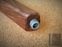 | ||
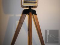
2. | Issue: | Placing the Claravox Stand on wooden- or ceramic tile floor is not advisable because the applied glides consist of hard plastics (black) which may cause scratches on the floor. In addition, the CV-C Theremin instrument slides even when slightly pushed because there is no grip provided (even on carpet) by the glides (as the name indicates). Theremin instruments have to be kept as fixed to the intended position as possible, moving even accidentally, especially during a performance, has to be prevented under all circumstances. |
Solution: | All glides have to be replaced by standard soft-rubber foots (gray) as used e.g. for electrical equipment. Those foots can even be tightened using standard wood screws through the metal thread-hull because it is not closed at the inner end. | |
Pictures: | 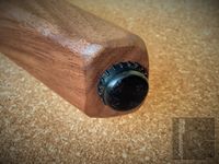 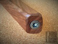 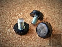 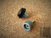 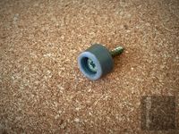 |
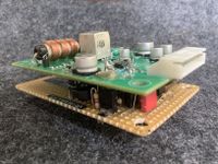
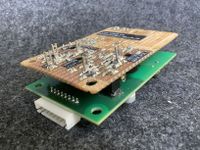
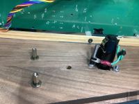
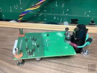
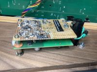
Claravox Theremin PCB Fixture
(03.11.2023)
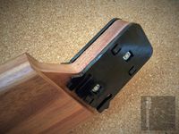
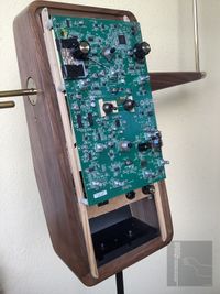
To access the main board of the Claravox Theremin easyly, a fixture was prepared. It consists of two wooden laths and a wooden plate, screwed to the housing. The pictures below show the assembly.
 |  |
 |  |