Theremin Construction Advice
For those who like to build their own Theremin by themselves, hints will be given in the following descriptions to overcome the obstacles which can be arise during construction. When following the advice given by the author according the experiences gained over the years, it is likely that the constructed Theremin instrument will be perform as expected.
Developing a good sounding, playable Theremin instrument is not an easy task because it is not a simple beat frequency oscillator. It does not generate sort of pure-sine tone, nor does it distort the generated audio signal to re-filter it. Thus, it does not apply the principles of early synthesizers which usually generate a sawtooth wave-form, which is processed by various filters (formant, low-pass, high-pass).
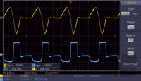
The instruments of Leon Theremin generate single-sine like pulses which vary in pulse-pause ratio according to the pitch. These pulses are fed to a limiter-amplifier that converts them to a nearly rectangular double pulse waveform, where one of the pulses is of positive- and the other of negative polarity. The generated rectangular double-pulse is separated from the following pulse by the pulse-pause.
To reduce the amount of developing effort, the author focused on understanding the real essential fundamental functionality of the instruments designed and build by Leon Theremin for C. Rockmore and L. Rosen, to reconstruct and redesign circuits applying components available today, which provide comparable performance in playability and sound quality.
The intention of the author is to enabled the hobbyist to construct a Theremin instrument using available components at hand (like ferrite cores, transformers, tubes, antenna-rods, transistors). Therefore, there are given no part lists or calculated values for the number of coil windings which would only match a specified ferrite core. The values in the schematics may serve as starting parameters to be modified according the requirements arising from the applied components.
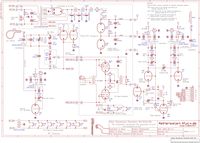
Currently, the circuit diagram of the 2017 Rockmorizer Silicon Theremin prototype instrument is under preparation for documentation purpose. Due to the prototype status, the schematic includes components and interconnections which could be omitted in the release of the instrument documentation. It is planned to compile schematics and descriptions which do not document the prototype status but present the essential circuits which can serve as the fundamental for the builder to construct a Rockmorizer Theremin instrument according to the principles as used by Leon Theremin in his instruments.
As long as the 2017 Rockmorizer Silicon Theremin documentation is not available, the provided schematics of the 6SH2P or 6SH2P-X Tube Theremin as well as the documented modifications as applied to the Etherwave Standard or FRANZIS Theremin, may serve as guideline for the interested Theremin hobbyist.
Theremin Coil Construction
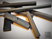
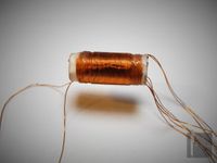
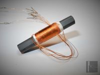
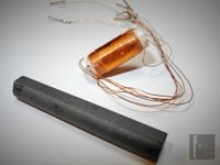
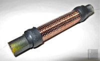
The main issue in Theremin construction is the preparation of the antenna- and oscillator coils. The author recommends to use readily available standard ferrite cores (as used for radio-controlled alarm clocks) with added bobbin which carries the coil windings. Ferrite cores are shown in the picture. The amount of windings has to be matched to the applied core material, thus the author cannot provide the adequate number; the coil has to be constructed by the builder to comply with the given inductance values, according the hints provided.
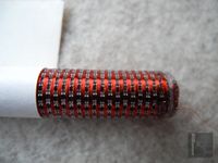
To construct the bobbin of the pitch- and volume oscillator coils of the Theremin, a layer of paper can be wound on top of the ferrite core while gluing the layers of paper, to form a cardboard tube which holds the movable core inside. Of course, the core must sit quite tightly inside the bobbin to not slip out by itself. The enamelled copper wire of the coil windings is wound on top of the paper-bobbin. To achieve a symmetrical coil of the two necessary windings, the wires are wound side by side at ones in one winding procedure. According to the diameter of the wire and length of the bobbin / core, it may be necessary to form a multilayer winding.
The core has to be somewhat longer than the bobbin / area of the windings. It is advisable to have the core always located inside the winding area. It is important to be able to adjust the distance and orientation of the oscillator coils to each other to achieve the correct RF coupling and compensation effects.
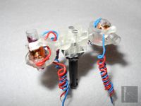
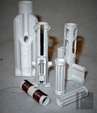
The author therefore uses 3D printed pivots which hold small coil-bobbins with adjustable ferrite cores as shown in the picture. The bobbins are not readily available; the author acquired a large amount of them at a local flea-market. The bobbins originated from a company liquidation. The contained ferrite cores are originally intended for a higher working frequency, thus having relatively low Relative Permeability Factor (µr) which makes it necessary to have many windings.
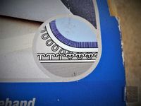
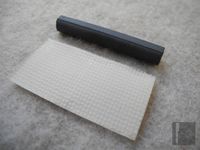
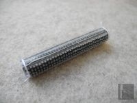
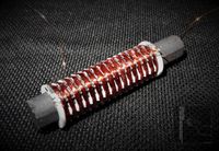
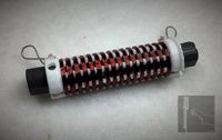
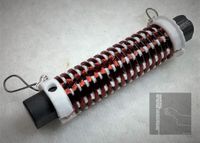
For the antenna extension coils of the pitch- and volume circuits, the bobbins have to be divided into many separated sections of windings to achieve sufficient low distributed capacity and thus a high self resonance frequency (SRF). The core has to be slide-able inside the bobbin for adjusting the coil inductance during alignment. Of course, the core must sit quite tightly inside the bobbin to not slip out by itself. To construct the bobbin of the antenna extension coils, a layer of paper is wound on top of the ferrite core while gluing the layers of paper, to form a cardboard tube which holds the movable core inside. On the outside of this paper-tube, a special self-adhesive tape which has burls on its surface, is fitted. This ‘hook-and-loop’ tape, as shown in the pictures, is originally intended to fix carpets on the ground.
The enamelled copper wire of the coil windings is placed in-between the burls. The core has to be somewhat longer than the bobbin / area of the windings. It is advisable to have the core always located inside the winding area. To achieve the necessary inductance of the antenna extension coils (which is quite high), e.g. two ferrite rods may be glued to each other at their ends, using e.g. instant adhesive, to form a single long core. The pictures show some of the constructed antenna extension-coil prototypes.
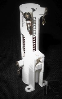
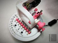
In the new Theremin instruments, the author uses 3D printed coil-bobbins which are housed in a antenna extension-coil assembly which contains means to conveniently adjust the ferrite-core inside the coil, as can be seen in the pictures below:
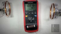
The coil bobbins can be attached to the 'Tiny Coil Winder' described below to be wound conveniently. The pictures show the measurement of inductance value, quality factor, DC resistance and determination of self-resonance frequency of an antenna extension coil of 122mH.
The self-capacitance (lumped / distributed capacity) of the coil was calculated to be 0,8pF @ 519kHz.
Tiny Coil Winder - Spulenwickelmaschine
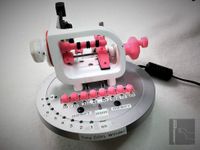
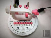
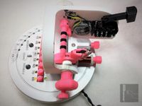
The 'Tiny Coil Winder', which is mainly constructed applying 3D printing techniques, is intended to be used to wind low distributed capacity (high SFR) Theremin antenna extension coils. The special bobbins to be used with the coil winder are 3D printed.
The 'Tiny Coil Winder', which was mainly constructed applying 3D printing techniques, is intended to be used to wind low distributed capacity (high SFR) Theremin antenna extension coils. The special bobbins to be used with the coil winder are 3D printed.
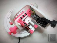
The 'Tiny Coil Winder', realized in 2017, enables the user to greatly reduce the time for realizing various values (up to 150mH of typically 0.8pF distributed capacity) of ferrite core type Theremin antenna-extension coils. The unit consists of recycled parts out of the ‘Bastelkiste’ (‘spare part box’ ?) and 3D printed components.
To count the windings, a circuit applying mainly two 4017 MOS digital-counters and some additional transistors is used. The counter preset- and actual value are indicated by yellow and green LEDs. The count pulse is derived from the turning wheel by a photo-sensor. Wheel and spindle are driven by a little, reused CD-ROM drive loading motor via belt-drive. The counters are preset to the desired count of windings by switches. Another switch has to be depressed as long as the spindle shall turn. Two switches reset the counters to the start value when pressed simultaneously, refer to the pictures. The added mechanical counter was only added for counting control purposes.
The 'Tiny Coil Winder' was only constructed for functionality, not for beauty or perfection. It is quite useful and works well.
Applying Line-Transformers as Theremin Interstage Transformers and AF-Chokes
According to Leon Theremin’s original design, at least one AF interstage-transformer has to be applied to generate the proper audio pulse-form. Because interstage transformers and AF chokes are uncommon today and very costly, attempts have been made to apply small standard line transformers at Theremin stages where these inductors are of essential importance for sound creation. At the presented evaluated circuits, the following readily available transformers have been used:
Hammond Type 229E230
ERA Type BV030-2461.0
Nevertheless, other transformers of appropriate inductance and lumped capacity may be usable, too.
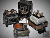
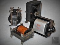
The following pictures show some vintage 1920s interstage transformers:
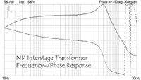
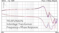
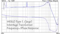
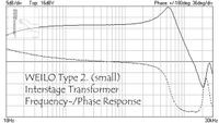
The pictures below indicate the frequency- and phase-response of the shown vintage interstage transformers (Telefunken, Weilo, NK).
Theremin Hand to Antenna Distance Indicator Device (THADID)
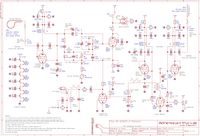
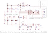
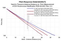
For evaluating a Theremin’s pitch and volume response, a simple distance indicator device (THADID) was developed which outputs an audio beep (AF burst) signal of 1.6kHz for every centimeter of hand movement towards the Theremin antenna. The schematic is shown below.
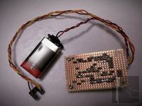
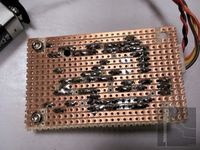
The circuit, which is kept as simple as possible, consists of a simple phase-shifter sine oscillator around Q1, continuously running at 1.6kHz. The modulated oscillator transistor’s collector current flows through the infrared LED of the photo-interrupter / coupler device (IC1). IC1 contains a infrared LED and a infrared sensitive photo-transistor. This transistor is connected in emitter follower configuration. When uninterrupted, the 1.6kHz sine amplitude modulated light of the LED is detected by the photo-transistor, causing a equally modulated current through resistor R9 and a corresponding audio signal at the output cinch jack (J5). The trimmer R8 has to be adjusted for best curve form of the sine signal; this is necessary because of the non linear photo-interrupter / coupler device which is not generally qualified for analog operation. The coupler’s AF output is additionally band-pass-filtered by components C6, C7 and R10 to improve the signal. The circuit is supplied by a single 9V battery and can be activated, which is indicated by LED D2, via switch S1. The next pictures show the PCB of the THDID prototype.
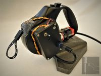
To simplify the mechanic of the Theremin Hand to Antenna Distance Indicator Device (THADID), the photo-interrupter / coupler device was disassembled and mounted to the inlet of a retractable belt dog leash as shown in the pictures. The circuit board was mounted into a small plastic housing (there wasn’t a appropriate housing at hand which could hold the battery inside), attached to the retractable belt dog leash device. To provide a stable mount, an old microphone-stand was used.
The belt of the leash was perforated every 10 millimeters over a distance of approx. 2 meters, using a punch pliers. For smoothing the holes, the belt had to be very slightly melted using a soldering iron. When correctly adjusted, the modulated infrared light beam leaving the LED is radiated through the holes of the leash, causing the audible beep signal. When the light is shadowed, the signal is widely attenuated. To improve the device and simplify the mechanics, a reflection-sensor device could be used instead of the photo-interrupter, which then detects white/black stripes painted onto the belt of the leash.
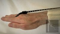
For the pitch response measurement, the THADID device is placed at the height of the (right) shoulder behind the player, e.g. by setting it onto a speaker stand. The lug of the belt has to be slipped over a finger of the player’s hand. The hand and arm of the player must be aligned to become a straight line when fully stretched out touching the Theremin’s antenna and the belt has to smoothly slide out- and into the mechanical dog leash device at the pitch sweep.
For the volume response measurement, the THADID device is placed on the floor below the Theremin’s volume antenna, guiding the belt through the volume antenna lug. The lug of the belt has to be slipped over a finger of the player’s hand. The hand and arm of the player must be aligned to let the belt become a straight line when touching the Theremin’s antenna as well as when holding the hand at the largest possible distance over the antenna. The belt has to smoothly slide out- and into the mechanical dog leash device at the volume sweep.
The THADID’s audio distance indication signal as well as the Theremin’s audio output have to be recorded (left & right channel) during measurement and evaluated later using audio manipulating software. The mean of the Theremin’s pitch has to be measured during the indication 1.6kHz burst. Same principle for volume response evaluation, but measuring the Theremin’s volume mean level during the indication 1.6kHz burst. Of course, the analysis of the audio signals of the Theremin pitch and volume measurement could be automated via a dedicated software sometime.
Essential Measurement Equipment for Theremin Construction
It is essential to have access to the following equipment:
- 20MHz Standard Digital Oscilloscope with frequency counting- and FFT capability (or comparable analog oscilloscope with analog channel output to add an external frequency counter)
- Impedance Measurement Device (LCR-Meter; capable of at least 100kHz measurement frequency, for inductance and capacitance evaluation)
- Universal Multi-meter (for voltage, current and resistance measurements)
- For antenna-extension coil self-resonance frequency (SFR) testing, a RF generator is recommendable. To test the audio response of circuits like amplifiers, a low-frequency generator (at least capable of sourcing sine- and square-waves) is useful.
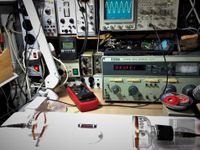
All of the essential equipment can be of lower quality because it is not necessary to perform highly accurate measurements – but none of the devices can be omitted during Theremin construction. It is advisable to look for (high-quality) vintage used measurement devices to reduce cost. A usable digital oscilloscope of Chinese origin is currently sold for approx. 175€ in Germany (11.2020).
Recommendable are digital audio recording equipment and PC software to analyze the recorded Theremin audio-signal via FFT (e.g. Adobe Audition 3.0) for spectral comparison to e.g. the Rockmore / Rosen instrument sound spectra.
