Theremin Measurements
Introduction
Measurements have been performed on certain Theremin circuity.
The presented diagrams are associated to the descriptions of: 'General Functionality of the Rockmore- and Rosen- Tube-Theremin Instruments according to Leon Theremin’s Design'
Audio Pulse-Width / Duty-Cycle and Sound-Spectrum of EW-REB 12-2020
Circuit: EW MOD 12-2020 of EW Standard Theremin Modifications
The sound spectrum of the modified EW/EW+ Theremin instrument consists of the lower-, mid- and high-pitch segment which slightly changes with volume. The spectrum is dependent on the pulse width (duty cycle). The diagrams below show the pitch dependent pulse-width and duty-cycle characteristics of the EW(+) with added EW-REB 12-2020 extension board.
f [Hz] | Pitch | PD (T) [ms] | NW [ms] | Duty NW [%] | PW [ms] | Duty PW [%] | PD / NW | NW / PW |
27.5 | A0 | 36.364 | 6.2 | 17.1 | 30.164 | 83.0 | 5.9 | 0.2 |
55 | A1 | 18.182 | 4.1 | 22.6 | 14.082 | 77.5 | 4.4 | 0.3 |
110 | A2 | 9.091 | 2.24 | 24.6 | 6.851 | 75.4 | 4.1 | 0.3 |
220 | A3 | 4.545 | 1.12 | 24.6 | 3.425 | 75.4 | 4.1 | 0.3 |
440 | A4 | 2.273 | 0.55 | 24.2 | 1.723 | 75.8 | 4.1 | 0.3 |
880 | A5 | 1.136 | 0.26 | 22.9 | 0.876 | 77.1 | 4.4 | 0.3 |
1760 | A6 | 0.568 | 0.098 | 17.2 | 0.470 | 82.8 | 5.8 | 0.2 |
As can be seen, the duty-cycle (Duty NW) of the mid pitch-range is typically 25%, corresponding to a pulse-ratio (PD/NW) of 1:4. The lower-register shows a decline of the duty-cycle below 110Hz (A2), corresponding to a pulse-ratio up to 1:6. The upper-register shows a sharp decline of the duty-cycle above 880Hz (A5), corresponding to a pulse-ratio up to 1:6.
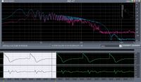
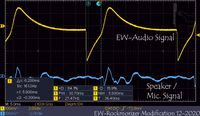
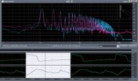
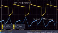
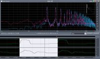
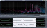
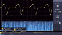
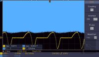
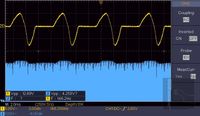
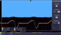
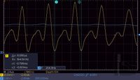
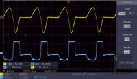
The following pictures show selected audio pulses and the resulting spectra. For signal comparison, the EW audio-output signal (upper trace, yellow) and the speaker output as received by a microphone (lower trace, blue) are displayed at the oscilloscope screen-picture at the right.
EW-REB 12-2020 Theremin Pitch A0 27.5Hz | |
EW-REB 12-2020 Theremin Pitch A1 55Hz | |
EW-REB 12-2020 Theremin Pitch A2 110Hz | |
EW-REB 12-2020 Theremin Pitch A3 220Hz | |
EW-REB 12-2020 Theremin Pitch A4 440Hz | |
EW-REB 12-2020 Theremin Pitch A5 880Hz | |
EW-REB 12-2020 Theremin Pitch A6 1760Hz |
The sound file of the recorded pitch-sweep used for pulse-width measurement, which holds the signal of the EW audio output on the left and the speaker signal, captured by a microphone on the right channel, can be downloaded below:
Pitch RF-Oscillators
Under construction!
Pitch Antenna and Extension Coil
Circuit: RT-6SH2P-Schematic of the RT-6SH2P Tube Theremin
Notes: The circuit applies the general tube circuitry (alike those of the Rockmore / Rosen Theremin) of the pitch-oscillators, the phase-detector and the limiter amplifier. Russian 6SH2P/6J2P (6AS6) have been used. Anode (plate) Supply voltage was +40V.
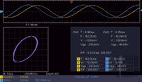
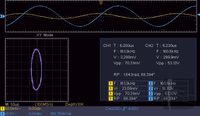
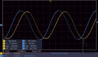
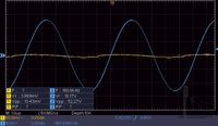
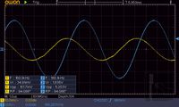
Description: The oscilloscope screen views below of the 6SH2P tube Theremin measurement show the input voltage, current and their phase-relation of the antenna extension coil at various distances of the hand to the pitch antenna. Approaching the antenna reduces the inductive current, touching leads to capacitive current. Zero current appears a few millimeters from the antenna, not touching it.
Ch.1 (yellow): 2mA/DIV antenna extension coil input current of the 6SH2P tube Theremin measurement
Ch.2 (blue): 1V/DIV antenna extension coil input voltage of the 6SH2P tube Theremin measurement
Ch.1 (yellow): 2mA/DIV antenna extension coil input current of the 6SH2P tube Theremin measurement
Ch.2 (blue): 1V/DIV antenna extension coil input voltage of the 6SH2P tube Theremin measurement
Pitch Phase Detector
Circuit: RT-6SH2P-Schematic of the RT-6SH2P Tube Theremin
Notes: The circuit applies the general tube circuitry (alike those of the Rockmore / Rosen Theremin) of the pitch-oscillators, the phase-detector and the limiter amplifier. Russian 6SH2P/6J2P (6AS6) have been used. Anode (plate) Supply voltage was +40V.
Description: The oscilloscope screen views below of the 6SH2P tube Theremin show the phase-detector RF input voltages at the detector-tube control- and screen grid (detail of the amount of amplitude variation - unsymmetrical upper and lower RF envelope) and the output voltage (single-sine pulse) at the secondary of the first interstage-transformer. The control-grid of the tube shows the largest AM like RF amplitude variation (grid current).
Ch.1 (yellow): 5V/DIV AF output voltage of phase-detector stage of the 6SH2P tube Theremin measurement
Ch.2 (blue): 1V..2V/DIV RF input voltage @ detector-tube control- and screen grid of the 6SH2P tube Theremin measurement
Description: The oscilloscope screen views below of the of the 6SH2P tube Theremin measurement show the anode (plate) current of the phase-detector tube (RF current pulses) through the first interstage-transformer and the resulting output voltage (single-sine pulse) at the secondary.
Ch.1 (yellow): 500uA/DIV anode (plate) current of phase-detector tube of the 6SH2P tube Theremin measurement
Ch.2 (blue): 2V/DIV AF output voltage of phase-detector stage of the 6SH2P tube Theremin measurement
Pitch AF Limiter Amplifier
Circuit: RT-6SH2P-Schematic of the RT-6SH2P Tube Theremin
Notes: The circuit applies the general tube circuitry (alike those of the Rockmore / Rosen Theremin) of the pitch-oscillators, the phase-detector and the limiter amplifier. Russian 6SH2P/6J2P (6AS6) have been used. Anode (plate) Supply voltage was +40V.
Description: The diagrams below of the 6SH2P tube Theremin measurement show the AF output voltage of the phase-detector stage (single-sine pulses) at the secondary of the first interstage-transformer and the limited resulting AC-coupled output voltage (limited single-sine pulse) at the anode (plate) of the voltage controlled limiter-amplifier tube.
Ch.1: 5V/DIV single-sine audio signal @ secondary of first interstage-transformer (phase-detector output) of the 6SH2P tube Theremin measurement
Ch.2: 2V/DIV limited single-sine audio signal @ output of limiter-amplifier of the 6SH2P tube Theremin measurement
Volume Detector
Under construction!
Volume Oscillator
Under construction!
Volume Antenna and Extension Coil
Under construction!
AF Power Amplifier (PA)
Under construction!
Speaker
Under construction!
Pitch Indicator
Under construction!
Power Supply
Under construction!
Tubes
Under construction!
Coils
Under construction!
Audio Transformers
Under construction!
Sound Analysis
Under construction!
