Theremin Instruments 'Termenvox' ('ТЕРМЕНВОКС')
according to L.S. Termen (aka Leon Theremin)
The instruments denoted here as 'Termenvox' base on the circuitry according to the information published in the Russian model building magazine 'Modelist Konstruktor' by S. Zorin, which is assumed to describe the last instrument version designed and built by Leon Theremin himself.
Modelist Konstruktor 1981-4 Termenvox | Noval-Theremin |
Discussion of Theremin Building Instruction 'S. Zorin: Termenvox - Modelist Konstruktor No. 4 1981, p. 23-25' (19-07-2023)

In issue No. 4 of 1981 (pages 23 to 25) of the Russian model building magazine 'Modelist Konstruktor', theremin building instructions 'Termenvox' were presented by the author S. Zorin ('ТЕРМЕНВОКС', С. Цорин, МОДЕЛИСТ КОНСТРЧКТОР 1981 № 4). In the same issue (pages 21 to 22) there is another article by the author, describing the life story of L. S. Termen (aka Leon Theremin; L.T.), which is closely connected to the development of his Termenvox instrument. This article is apparently based on an interview with L.T. : 'Pages of History: Sound - disembodied' (страницы истори: 'свободно из простран - ства Вышедший звук‘, С. Цорин, МОДЕЛИСТ КОНСТРЧКТОР 1981 № 4).
In order to be able to discuss the circuit and the structure proposed there, the original Russian article had to be translated first. There were errors in the text that were corrected. Unfortunately, there were also numerous errors in the original circuit diagram, which made it impossible for the circuit shown there to function correctly. The information about the coils is also partly dubious. For these reasons, a new circuit diagram has now been created that contains the suggested corrections, additions and component values. For example, the decoupling capacitors of the heating circuit and the output voltage of the transformer for negative auxiliary voltage generation have been added.
The circuit, in particular the peculiarities of the oscillators, the use of extension coils, the mixer used and also the linguistic formulation, which sounds like the transcript of an interview, seem to indicate Lev Termen's collaboration, who probably had been interviewed by the Author S. Zorin. The instrument demonstrated by L.T. during his last trip to the US in the 1990s (which he had been using since the 1950s, as can be seen from film documents) was apparently the basis for these building instructions. This is possibly the improved prototype made by Termen himself. However, the arrangement of the components and the coils in the 'assembly instructions' do not match the well-known photo of the internal structure of this instrument. The oscillator coils presumably have a significantly higher number of turns and inductance there.
The Russian article is not so much a detailed assembly instruction as a description of the basic function and construction, as apparently stated by L.T. himself and documented using the existing prototype. It would thus represent the only known description documented according to L.T. statements.
There are the notes of L. Rosen, resulting from interviews with L.T. , as well as an incomplete circuit-diagram. Described there is the vastly improved theremin instrument, built by L.T. for L. Rosen and C. Rockmore in the US during the 1930s. Also worth mentioning is the circuit-diagram created by R. Moog in the 1970s while restoring the Rockmore theremin. This schematic is also incomplete; the adjustment wheel on the left of the device and the 440Hz pitch-indicator were not documented.
The (corrected) circuit discussed here has not yet been implemented as a test setup to check the correct function and the component values to adjust them if necessary (as of July 2023).
Characteristics of the Theremin instrument
- Prototype of L.S. Termen (1920s)
- 1930s Instrument (RCA)
- Current modified version (1950s)
The theremin instrument described in the assembly instructions should be able to be configured for the pitches soprano, alto, tenor and bass over 4.5 octaves. The pitch is controlled by the horizontal movement of the right hand towards the vertical rod antenna, the vertical movement of the hand along the antenna rod should have no effect on the pitch. With the left hand, the volume of the sound is controlled in the usual way by moving the palm up and down over the second antenna, which consists of a horizontal metal loop. The distance between the two antennas should correspond to the arm length (70 to 90cm). By moving the hands in the horizontal (pitch) and vertical (volume) level, the capacitive influence of the hand positions to each other should be minimized.
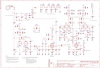
Circuit Diagram
The volume control and the power-amplifier are not functional in the original circuit diagram. R1 has to be connected to the control-grid of V2 and ground, not in parallel with R4, R1=260k, R4=300k. R7 has to be connected in series with D3, resulting in a voltage divider of D3, R7 and R8 (in the circuit diagram, R103 was also added here), C5 has to be connected to the connection point of this divider. The parallel capacitor (C104) to L2 may be missing. These corrections are already included in the updated schematic shown below.
")
 | Modified Schematic Modelist-Konstruktor 1981-4 Theremin Schematic of Modelist-Konstruktor 1981-4 Termenvox-Theremin (corrected version) Zorin-1981-Theremin_SCH_0v1.pdf (130.86KB) |
Schematic of Modelist-Konstruktor 1981-4 Termenvox-Theremin (corrected version)
| Zorin-1981-Theremin_SCH_0v1.pdf (130.86KB) |
Structure and Function
The basic structure and circuit function are described below.
Pitch Control

The pitch-antenna rod (L=50cm, D=10mm) should end slightly above the performer's head. The initial capacitance of the vertical antenna electrode for pitch control is said to be around 10pF and doubles as the hand approaches it (the original text stated 100pF here, which is much too high for the pure antenna capacitance to ground).
Pitch Oscillators
The two slightly coupled radio-frequency (RF) oscillators of the Hartley type ([47] 'Radio Technology without Burden', Otto Liemann, 10th edition, Franzis-Verlag, Munich, 1969; Figure 9.17 'Three-point circuit with series feed' / [37] 'The Reception of Short Waves', H. Guenther / H. Kroencke, Franckh'sche Verlagshandlung W. Keller & Co, Stuttgart, 1926; Chapter 21 'The practical implementation of the Armstrong circuit', Figure 25) generate signals, which are referred to as 'beat notes'. The frequency of one of the oscillators is constant, that of the second should change in proportion to the change in effective capacitance of the vertical pitch antenna rod as the hand approaches it. Since these oscillators could cause radio interference, their frequency should not exceed 180kHz.
Coupled Resonant-Circuits, Pulling
In order to be able to cover 4.5 octaves of pitch-range, the frequency of the controlled RF oscillator (V9) has to be changed significantly. The principle of 'pulling' the frequency of two oscillating circuits is applied; this is described in [38] 'The pulling phenomenon' ('The Textbook on High-Frequency Technology, Volume II, F. Vilbig, 4th Edition, Akademische Verlagsgesellschaft Becker & Erler, Leipzig, 1944, Chapter 9-1-G).
These coupled oscillating circuits consist of the parallel oscillator tank of tube V9 (L7, L8, C21, C23) and the series oscillating circuit of extension coil L9 with its lumped capacitance (which should be kept as low as possible), as well as the capacitive acting rod-antenna (W2). This resonant system is called a quarter-wave resonator, 'which, near its resonant frequency, multiplies the capacitive component of the antenna acting on the oscillator circuit'. However, the entire series resonator circuit, consisting of antenna and extension- coil, acts as an apparent variable inductance (and not as an apparent capacitance), which is connected in parallel with one sub-coil of the oscillator resonant circuit; this behavior has already been described several times at www.Aetherwellen-Musik.de .
Caused by the approach of the hand in a position close to resonance, the influence of the antenna capacitance on the frequency of the RF oscillator could increase dramatically due to the phenomenon of 'pulling' between the two resonant circuits. If the coupling between the RF tube oscillator (V9) and the antenna resonator, which is formed by the capacitive antenna and the extension-coil with its own lumped capacitance, close to the antenna-resonator resonance, is to strong, the oscillator frequency could jump abruptly to the antenna resonator-frequency, as is also stated in [38] ('The Textbook on High-Frequency Technology, Volume II'; see above) and in [45] 'Simultaneous excitation of several frequencies, frequency hopping' ('The Handbook of High-Frequency Technology', H. Meinke / F.W. Gundlach, 2nd Edition, Springer-Verlag, Berlin / Goettingen / Heidelberg, 1962, Chapter R-11). For this reason, this coupling must not become too strong, or the resonant frequency of the antenna-resonator must remain far enough below the RF oscillator's frequency. However, the pitch-antenna sensitivity to hand motion decreases with increasing frequency spacing. This coupling and frequency setting also depends on the quality-factor of the coils used; it is very critical and requires a lot of understanding and patience when adjusting to get a good linear pitch range.
Coils
The specified coil winding-data and the resonant circuit capacitors specified in the original circuit diagram could not always be brought into line with the usual theremin frequencies (170kHz, 260kHz, 450-470kHz). It can be assumed that some of the inductance values or the specified winding-data are incorrect and cannot be used, but the specifications of the oscillator-tank capacitors are correct. Therefore, the coils were recalculated. In the assembly instructions it is repeatedly pointed out that the data for the coils, in particular L3 to L8 (as well as for capacitors C16 and C23), are only approximate and that the actual number of turns can only be determined when the instrument is adjusted. The value of the oscillating circuit capacitors must also be adjusted if necessary according to the lumped capacitance of windings, lying one on top of the other, which can be significant and depends on the mechanical structure. The following calculators were used for the subsequent calculation of the air coils:
http://electronbunker.ca/eb/InductanceCalc.html
http://www.df7sx.de/luftspule/
http://electronbunker.ca/eb/InductanceCalcML.html
Antenna-Extension Coils

The antenna-extension coils L1 for volume (according to calculation based on the original winding data, the inductance is around 72mH with number of turns N=2550) and pitch L9 (according to calculation based on the original winding data, the inductance is around 85mH with number of turns N=2950). According to the instructions, they are single-layered, applying enamelled copper wire 0.1mm, wound over the entire length of the bobbin with a diameter of 60mm and a length of 29.5cm (L1) or 34.0cm (L9). A distance of 8-10 mm should be provided on both sides for connection terminals. The windings should also be protected from mechanical damage by two to three layers of varnished fabric or varnished paper. Since the resonant frequencies of the volume- and pitch-antenna circuits should normally differ significantly in order to minimize mutual interference, the winding data specified for the volume-antenna coil are very likely to be incorrect.
Pitch-Oscillator Frequency 180kHz
With a pitch-oscillator frequency of 180kHz, the antenna capacitance should be around 9.2pF using an 85mH antenna coil inductance, which comes very close to the specified 10pF. With an antenna capacitance of 10pF, the antenna-resonator frequency is 173kHz (coil 85mH), i.e. below the oscillator frequency, which is correct.
Volume-Oscillator Frequency 260kHz
With a volume-oscillator frequency of 260kHz, the antenna capacity using 72mH antenna coil inductance should only be about 5.2pF, this seems too low. For a typical theremin volume-oscillator frequency of 260kHz, the inductance of the antenna-coil should be about 37.5mH with an assumed antenna capacitance to ground of 10pF. This results in a number of windings N=1400 and a winding length of 16cm.
Can the Volume-Oscillator Frequency be 470kHz?
If the typical volume-oscillator frequency is set to 470kHz, the antenna capacity at 72mH antenna coil inductance should only be around 1.6pF! This is not practicable.
With an inductance of the volume-antenna-coil L1 of about 14mH and an assumed antenna capacity of 8pF, the resonant frequency of 470kHz is reached; with the given bobbin diameter the coil has N=625 turns and the winding length is 72mm. It is therefore much more likely that the volume oscillator frequency should be around 260kHz, since this is still a suitable resonance frequency, which must stay slightly below the oscillator frequency. Even with the original winding data, taking into account a lower antenna capacitance of around 5pF to 6pF, this can be achieved.
Volume-Detector Coupling-Coil

The coil L2 is to be wound with 30-40 turns and enameled copper wire 0.1mm in diameter on a coil body that can be slid over L1. This results in an inductance of about 186uH with N=35 and a coil body diameter of 66mm. It is then pointed out that the information is only approximate and the actual number of turns can only be determined during commissioning.
No parallel capacitance is drawn in the circuit diagram. At 260kHz, if the coil data is correct, a 2nF capacitor should be used, but this is unlikely due to the low L/C ratio. Generation of the volume control voltage is based on changing the volume-antenna circuit resonant frequency while shifting the volume-oscillator frequency as the hand approaches the antenna. Both resonant frequency changes support each other, so that there is sufficient sensitivity and bandwidth, despite the lack of a secondary parallel resonant circuit (there is only the coupling coil without a parallel capacitor, which sits on the antenna coil forming a transformer of low coupling factor); this is plausible.
Volume-Oscillator Coils
On bobbins similar to those used for the pitch oscillator coils, the coils L3 and L4 should be wound in opposite directions, at 60mm (original text 30mm) diameter with 20 (L3=47uH, N=20) and 30 (L4=100uH, N=30) windings of 0.15mm enamelled copper wire, respectively. The total inductance is then about 216uH (coupling factor 0.5). If the values given in the original text are used, the result is L3=23uH, L4=45uH and thus a total inductance of around 100uH. Together with the effective oscillating circuit capacitances given in the circuit diagram, which sum up to about 150pF, this results in a typical resonant frequency of 1.3MHz; this is much too high!
Corresponding to the parallel capacitance of typically 150pF, an oscillator frequency of about 500kHz results when using changed coil values (total inductance 675uH). This would fall within the expected range of typical theremin-frequencies around 470kHz. However, as explained above, the volume antenna-extension-coil is dimensioned for around 260kHz. For example, if the volume-oscillator is to oscillate at around 260kHz, the inductance must be around 2.5mH with parallel capacitor set to 150pF. Keeping 675uH, the capacitor needs to be 555pF. It is assumed that in the original text the coil-radius (30mm) was given instead of the coil-diameter (60mm). This results in about 47uH (N=20) for L3 and about 100uH (N=30) for L4. From this, the total inductance is calculated as 216uH (coupling factor 0.5). For 260kHz, a 1.7nF capacitor must be connected in parallel. In the schematic, a 120pF capacitor is connected in parallel and a 5pF to 100pF variable capacitor is used in parallel to the anode circuit (which therefore does not fully affect the oscillator-tank). If the assumption is correct that a 1200pF capacitor must be used instead of 120pF and the number of turns is correct, then together with the 216uH resonant circuit inductance, a resonant frequency of 313kHz results, which comes close to 260kHz; the oscillator frequency must be slightly above the antenna-series resonator-circuit frequency, which is therefore also correct. If a higher coil coupling factor is used for the calculation of the total inductance, the inductance increases and the resonant frequency decreases, i.e. comes even closer to the assumed frequency of 260kHz with the same capacitor value. The conclusion is that the necessary volume oscillator frequency of around 260kHz can be achieved by maintaining the number of turns (20 and 30) with a corrected coil-diameter to 60mm and using a 1200pF (fixed) capacitor. The value of the oscillator-tank capacitor must be adjusted, if necessary, according to the self-capacitance of stacked windings, which can be quite significant and depends on the mechanical structure.
Values for Vol.-Oscillator Coils, Oscillator-Tank Capacitor and Antenna-Coil
In the updated circuit diagram, oscillator-coil values of (120+60)uH were selected, which result in a total inductance of 300uH with a coupling factor of 0.7. Together with the decisive resonant circuit capacitor of 1.2nF, a volume oscillator frequency of 265kHz is achieved. With an antenna capacitance of 6pF and an antenna extension coil of 70mH, the frequency deviation is up to 1kHz.
Pitch-Oscillator Coils
The pitch oscillator coils L5 and L7 (anode circuit) should be covered with a layer of paper, L6 and L8 (grid circuit) should be wound over them in opposite directions, each with 0.15mm enameled copper wire. With the winding data given in the original text (bobbin diameter 30mm, length 50mm, number of windings L5/L7=60; L6/L8=40), the result is L5/L7=136uH and L6/L8=72uH. The total inductance is about 307uH, the resonant frequency is 257kHz with a parallel capacitor of 1.25nF. The resonant frequency should be between 170kHz and 180kHz (according to the antenna-resonator circuit), this is obviously too high!
Using bobbins of 60mm diameter, coil values are L5/L7=360uH and L6/L8=185uH. The result is a total inductance of about 800uH and with paralleled capacitor of 1.25nF a resonant frequency of about 160kHz, which is a bit too low. Applying bobbins of 50mm diameter, coil values are L5/L7=280uH and L6/L8=145uH. This results in a total inductance of about 625uH (coupling factor 0.5) and a resonant frequency of about 180kHz applying capacitor of 1.25nF, which is a bit too high. If the coupling factor is slightly higher, the total inductance increases and the resonant frequency decreases slightly. The value of the oscillator-tank capacitor must be adjusted, if necessary, according to the self-capacitance of stacked windings, which can be quite significant and depends on the mechanical structure.
Values for Pitch-Oscillator Coils, Oscillator-Tank Capacitors and Antenna-Coil
Generally, coils are difficult to calculate; there are various formulas and solutions. The following data was determined, which can serve as a guideline: With bobbins between 50mm and 60mm in diameter and 0.15mm enameled wire, the coil values are L5/L7=145uH with N5/N7=40 and L6/L8=235uH with N6/N8=50. This results in a total inductance of about 640uH (at a coupling factor of k=0.7). In order to compensate for fluctuations in humidity and temperature, the coils of the pitch-oscillators must be identical. In the updated circuit diagram, the pitch-oscillator coil values of (235+145)uH, which result in a total inductance of 640uH (coupling factor 0.7), have been entered. Together with the oscillator-tank capacitors and the antenna-circuit, a pitch-oscillator frequency of 178kHz (hand away from antenna) is achieved. With an antenna capacity of 10pF and an antenna extension coil of 85mH, the frequency deviation should be greater than 1.6kHz.
Ferrite-Rods
Furthermore, it is pointed out that the antenna-coils L1 (72mH) and L9 (85mH) could also be wound on ferrite-rods with a length of about 140mm and a diameter of 10mm using 0.06mm enamelled copper wire. A layer of 1mm thick paper should be added between the winding and the ferrite-rod (12mm bobbin diameter). No winding lengths or number of turns were given. These depend heavily on the properties of the ferrite-antenna rods used; typically an initial permeability of 50 should be assumed. For L1=72mH with 12mm bobbin diameter, 0.06mm enameled copper wire and rod initial permeability of 50/100/300, the number of turns (N) is about 580/300/100 (winding length 40/20/8mm). For L9=85mH with 12mm bobbin diameter, 0.06mm enameled copper wire and initial permeability of 50/100/300, the number of turns (N) is about 690/340/120 (winding length 45/25/10mm). [39] 'Paths into Electronics' (J. Glagla / G. Lindner, Otto Maier Verlag, Ravensburg, 1980) was used for subsequent calculation of the ferrite coils.
Transformers
For T1 it should be possible to use an audio power-amplifier output-transformer (from a tube radio). The transformer T2, which generates the negative auxiliary-voltage, should deliver 30V on its secondary winding when 6.3V are present on its primary winding.
Tubes
The construction of the theremin instrument from 1921 (RCA) is described as no longer reproducible in 1981 (publication of the construction manual). Therefore, comparable (Russian) tubes should be used. Even if the type designations of the Russian tubes apparently correspond to American parallel types, there can still be deviations (e.g. socket or electrode wiring), as is e.g. the case with the 6A7.
The 6S2S triode used in the volume-oscillator corresponds to approximately ½ ECC82. The two systems of the ECC82 are not particularly shielded from each other, so two individual tubes (only one system each) would have to be used. It is unclear why the 6S2S triode was not used in the volume-oscillator also. Oscillator frequency and power differ only slightly; possibly the 6N9S double triode oscillator circuit was formerly used to drive a different volume control circuit with higher RF current requirements (e.g. RF tube heating as in the RCA theremin). The power tube 6P3S corresponds approximately to the 6L6.
Mixer-Circuit
The signals to be mixed are fed to the mixing heptode V8 type 6А7 (6А2P), whose control grids are connected to the control grids of the V7 and V9 oscillator tubes via resistors R16 and R19 of 10kΩ to 50kΩ each. Originally, there is no inductance (interstage transformer or choke) placed in the anode circuit to integrate the RF pulse generated there, as applied in the Rockmore/Rosen and RCA theremin. As a result, the RF pulse (burst) is routed via the limiter-amplifier tube and the output-stage tube to the output-transformer, which integrates the pulse (together with the parallel capacitor); the low-frequency pulse can then be picked up at the transformer's loudspeaker connection. In this way, large RF burst signals are routed to the power-tube and amplified, which can lead to significant interference. It is therefore more likely that at least one RC element, acting as RF filter in front of the power tube's grid, was left out in the circuit diagram. It was added to the updated circuit diagram (C103). At this point there is an error in the original circuit diagram anyway, since R1 and R4 are connected in parallel here, which is not plausible. An LC element, consisting of choke L100 and capacitor C107, was also added to the anode circuit of tube V8 to further reduce RF interference.
Audio-Spectrum and Coupling-Compensation
The composition of harmonics (overtones) in the output signal at the 6A7 (6A2P) mixing tube's anode and the degree of coupling between the oscillators should be adjustable by the values of the resistors (R16 / R19) on the control grids of V8. The fact that the composition of harmonics depends on the pulse-pause ratio of the audio signal is not mentioned, but reference is made to the coupling between the oscillators, which can be changed by selecting the capacitor values of C16 and C23 (tank capacitors of the oscillators) and changing the relative position of the oscillator coils L5 / L6 and L7 / L8 in relation to each other. Increasing or decreasing the distance as well as rotating can be used in order to adjust the bass range of the instrument. This (phase) compensation of the RF signals, coupling between the oscillators (which can lead to synchronization effects in the lower frequency range of the theremin), by mechanically changing the position of the oscillator-coils in relation to each other has already been described in detail at www.Aaetherwellen-Musik.de .
Antenna-Coil Adjustment
The antenna-coils (antenna-extension coils) are usually adjusted by starting with a large inductance value (full number of turns). The antenna-coil inductance is then reduced by unwinding turns (oscillator frequency repeatedly re-adjusted to the target value, e.g. 170kHz) until optimum hand sensitivity (full playing range) is achieved. With this procedure, the resonant frequencies are increasingly approximated to each other; that of the antenna circuit from low, that of the oscillator from high frequencies until they are close together without the oscillator frequency jumping when the hand approaches and touches the antenna. Even when switching the device off and on again, the oscillator frequency should not jump or get stuck at a different frequency than the one previously set. If this is the case, the frequencies of the oscillator and antenna-circuit are too close together and more turns must be added to the antenna-coil to increase the inductance. The oscillator frequency can also be changed experimentally until the jumping no longer occurs; provided the oscillator frequency remains in the desired frequency range. It is also possible to connect another small adjustable ferrite-coil in series with the antenna-coil in order to be able to carry out the adjustment more conveniently.
Volume Control

The signal from the mixing tube V8 is supplied to the volume control heptode V6 type 6A7 (6A2P). The amplitude of the negative bias on the first (original text: second) V6 control grid determines the volume of the sound. To contol it, the left hand varies the capacitance of the loop antenna W1, which influences the frequency of the oscillator tank (L1/C1). The oscillator that supplies the high-frequency for volume control applies the double-triode V4 type 6P9S (6P8S).
If the hand is at a distance of half a meter above the loop-shaped antenna electrode W1, the volume resonant circuit should be almost in resonance (highest volume). There should then be a positive bias of +1V to +2V on the second (and fourth) grid (the screen grids) of V6. Approaching the left hand detunes the resonance and is said to cause this bias to rise to +15V to +20V.
In the original text, the bias voltage should be +15V to +20V at resonance, corresponding to high volume. When lowering the hand and detuned resonance, the voltage should drop to +1V to +2V, corresponding to lower volume. This cannot be correct, since the tube V6 is increasingly blocked aside from resonance, i.e. low volume when the hand is brought close to the volume antenna, due to the strongly negative control voltage on grid 1. V6 is then increasingly blocked and thus hardly any anode and screen grid current flows. The screen grid voltage divider, at low volume is not loaded more, but less; the screen grid voltage thus increases. This is denoted as 'sliding screen grid voltage'.
The generation of the volume-control voltage is not discussed in the original text, so a brief description follows:
The auxiliary voltage generation around T2 and D3 generates a relatively constant negative voltage of about -25V, which can be adjusted at R8. This voltage is applied to the cold end of the volume-detector coupling-coil which is attached to the volume-antenna extension-coil. At full volume, the antenna resonator is in resonance and the RF amplitude at the coupling-coil is at maximum. This high-frequency voltage is rectified by D1, C2 represents the charging capacitor. The control-voltage, which depends on the hand distance to the volume antenna, is present at resistor R2. It is positive in relation to the cold end of the coupling-coil, which is grounded for high-frequency by C105. It is added to the negative auxiliary-voltage, i.e. it compensates for it. Measured against ground, this results in a volume-control voltage that should range from about -25V (quiet) to -2V (loud). The (negative) control-voltage is fed to grid 1 of V6 via the low-pass filter formed by R11 and C13. V6 will amplify more or less accordingly; if the voltage is strongly negative, the tube is blocked completely and no low-frequency signal reaches the output tube V2.
Influencing the Timbre
In the circuit description of the building instructions, circuits that influence the tone-color are reported, but these are not included in the original circuit-diagram. Resonance formant channels in the range from 500Hz to 3kHz are mentioned.
Power Amplifier
The audio signal is amplified by the output tube 6P3S (or 6P14P). In parallel with the primary winding of the output transformer T1 a 10nF capacitor (C8) is placed, which suppresses residual RF. Likewise, together with T1, it causes low-pass and resonance effects that influence the sound character of the theremin.
Adjustment Procedure
The variable capacitors C14 and C21, which are located behind the front panel (not described in detail in the assembly instructions), should serve to tune the instrument. If the hand is far away from the rod-antenna, the lower tone limit should be adjusted. If the hand is then brought closer to the antenna, the pitch should increase evenly. A wrong setting should have the opposite effect, the sound should get deeper as you approach. The volume should be influenced with the left hand, so that the maximum volume is obtained when raising about 30 to 40 cm and the minimum when lowering the left hand to about 8cm above the loop-shaped antenna W1. This also corresponds to the volume functionality of circuits already described in detail at www.Aetherwellen-Musik.de .
Mute-Switch
When the mute switch S1 on the front panel is actuated, it interrupts the audio signal (e.g. during breaks in playing). The tube circuits (especially the oscillators) remain in operation to prevent the need from warming up again.
Power-Supply, Interference-Suppression Measures and Grounding
The power-supply unit, which is not described in detail, should be able to deliver a well-filtered anode voltage of +250V to +300V at a current of 75mA to 100mA. The 150V stabilizer tube V5 at the circuit diagram, which supplies the pitch oscillators, is not discussed. The heating winding connections (6.3V / 2.5A) should be connected symmetrically to the device-ground through capacitors with capacity of 0.5µF. Another similar capacitor is connected from device-ground to the mains protective conductor (PE, earth). However, this is not shown in the original circuit-diagram. It is pointed out that this is necessary 'in order to obtain the correct position of the high-frequency voltage-node in the standing-waves of the antennas'. The high-frequency technically cold-end of the antenna-resonator circuit is grounded, as is the case with radio-transmitters, and the high frequency is therefore only fully effective at the hot-end, the antennas. The musician's hands can also be regarded as grounded via his body and the floor, even if this is only the case with very high resistance. Especially at the presented theremin instrument, which works with tubes and high voltages, the high-impedance grounding of the musician has little influence on the playing area, since high-frequency high voltages (up to a few hundred volts) are present at the antennas at resonance, which generate relatively large high-frequency currents between antenna and earth - hands and 'grounded' body of the musician. However, due to the skin effect, these are harmless to humans even if the antennas are touched; the high-frequency current only flows on the body surface. In addition, the voltages collapse immediately when touched, since there is then any resonance no longer.
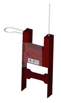
Stand

The completed Theremin in the U-shaped case, which is 45.5cm high, 42cm wide and 13cm in depth, should be placed on the stand provided for this purpose, which adjusts the height of the instrument to the height of the musician. The stand is 46cm high, 42cm wide and 13cm in depth.
Loudspeaker and Baffle
A speaker with power of 5 to 10W is to be mounted behind the center hole of a baffle of 55cm × 50cm. It should be placed about 1m away from the player's head. Below this baffle, which is supported by a tripod, the power-supply-unit (including mains cable, mains switch and fuses; not described in detail) should be mounted and connected to the instrument via cables and plugs. Baffle and tripod were not specified in the dimensional sketches.
Mechanical Construction
The original building instructions contain sketches from which the shape and dimensions can be taken; they are not reproduced here.
Housing and Stand
In the original drawings of the mechanical structure (drawing of the mechanical parts), the following components are included:
1 – Back Panel 445 x 420 x 5 (1x)
2 – Front Panel 445 x 420 x 5 (1x)
3 – Side Panel 445 x 120 x 5 (2x)
4 – Volume Antenna 300 x 10 with inner diameter 150 (1x)
5 – Ceiling Panel large 120 x 260 x 5 (1x)
6 – Inner Wall 120 x 210 x 5 (2x)
7 – Pitch Antenna 500 x 10 (1x)
8 – Ceiling Plate small 130 x 85 x 5 (2x)
9 – Bottom Plate 130 x 420 x 5 (1x)
10 – Stand Board 460 x 130 x 10 (2x)
11 – Stand Intermediate Board 150 x 400 x 10 (1x)
The dimensions are given in millimeters (mm) in the drawings of the building instructions, the U-shaped housing of the instrument should be made of 5mm thick plywood, the matching stand should be made of 10mm thick solid wood. Simplified dimensions are given here with length x width x height (L x W x H) or length x diameter (L x D).


Chassis

The chassis, which carries the electronic components, shall consist of a horizontal metal plate (400 x 100 x 4)mm fixed in the instrument-housing. It should carry the following components:
L1/L2 – Volume-Extension Coil 315 x 60
L9 – Pitch-Extension Coil 360 x 60
S1 – Mute Switch
V2 – Power Tube 6P3S
V4 – Volume-Oscillator Tube 6N9S
V5 – Voltage-Regulator Tube SG4S
V6 – Volume-Control Tube 6A7
V7 – 1st Pitch-Oscillator Tube 6S2C
V8 – Phase-Detector / Mixer Tube 6A7
V9 – 2nd Pitch-Oscillator Tube 6S2C
C4 – Volume-Tuning Capacitor
C14 – Pitch-Adjustment Capacitor
C21 – Pitch-Tuning Capacitor
R8 – Volume Cut-Off Trimmer
T1 – Power-Amplifier Transformer
T2 – Negative-Bias Transformer
All dimensions in the original drawings of the assembly instructions are given in millimeters (mm), the tube base cut-outs should have a diameter of 32mm. Simplified dimensions are given here with length x width x height (L x W x H) or length x diameter (L x D).
")
v")

")
")
")
")

")
| Discussion of Theremin Building Instruction 'S. Zorin: Termenvox - Modelist Konstruktor' GERMAN Diskussion der Theremin Bauanleitung „S. Zorin: Termenvox - Modelist Konstruktor Nr. 4 1981, S. 23-25“ deutsche Version Diskussion-Zorin-Modelist-Konstruktor-Theremin_4-1981_0v8.pdf (4.44MB) |
Diskussion der Theremin Bauanleitung „S. Zorin: Termenvox - Modelist Konstruktor Nr. 4 1981, S. 23-25“ deutsche Version
| Diskussion-Zorin-Modelist-Konstruktor-Theremin_4-1981_0v8.pdf (4.44MB) |
Noval-Theremin (20-07-2023)

The Noval-Theremin schematic shown below represents an approach to realize the ‘Modelist Konstrukor 1981-4 Termenvox’ instrument using common tubes and components.
There is no power amplifier included, so a relatively simple external power-supply can be used for anode-voltage (+90V DC) and filament-current (300mA DC).
Only two Noval type tubes ECH81 (6AJ8 /6I1P) and two Noval type tubes ECC82 (12AU7 / 6N10) are used. There are no component values given because the proposed circuit has not been tested yet (as of July 2023).
")
| Noval-Theremin Schematic Rev.0.2 NV Noval-Theremin Schematic Rev.0.2 without component values Noval-Theremin_SCH_0v2_NO-VALUES.pdf (107.72KB) |
Noval-Theremin Schematic Rev.0.2 without component values
| Noval-Theremin_SCH_0v2_NO-VALUES.pdf (107.72KB) |