General Functionality of the Rockmore- and Rosen- Tube-Theremin Instruments according to Leon Theremin’s Design
This paper is also available in German:
Diese Abhandlung wird auch in deutscher Sprache zur Verfügung gestellt:
‚Allgemeine Funktionsweise der Rockmore- und Rosen Röhren-Theremin Instrumente entsprechend Leon Theremin‘s Design‘ Version 1.1
© A. Klaus aetherwellen-musik.de 12.2021
Introduction
The circuit functions are not as simple as the well known schematics [3], [5] and the additional descriptions in [4], [6] of the C. Rockmore and L. Rosen Tube-Theremin instruments, designed by Leon Theremin, promise. Therefore, we have to dive somewhat deeper into the principles of the applied vintage electronics with all the component deficiencies and lumped effects.
The circuit and performance of the RCA Theremin [2] is very different (designed by L. Theremin according to RCA demands) and therefore not discussed here in detail.
Additional Statement
The issues discussed here are based on the available documents of Leon Theremin’s original instruments, the technical survey of those and own measurements performed on rebuild original circuitry. In addition, circuits and Theremin test-instruments have been build using different electronic parts like vintage tubes and modern silicon components, according to the findings of this ongoing research, which are believed to be close to the principles as used and invented by Leon Theremin. Circuit simulations have been performed, tests and measurements including audio spectrum-analysis have been made at the constructed equipment especially for recreating the ‘Rockmore’ instrument sound.
Even the well known Moog EW Standard Theremin has been reviewed and examined excessively (simulations, measurements) because of it’s sound and volume response, which leave a lot to be desired. The outcome of this optimization attempt is described in detail in chapter EW Standard Theremin Modifications.
The research is running for more than ten years now, with setbacks and achievements – findings are now documented at aetherwellen-musik.de, even if not complete or perfect.
Currently it seems impossible to do professional measurements at the original instruments to have concluding confirmation that the issues and findings presented here are correct. As long as there is no validation, only the sound generated using the presented principles can be evaluated by comparison to e.g. the recordings of Clara Rockmore. When ever possible, affirmation has been tried to gain in the related literature. The used literature is listed for detailed re-examination of special issues which cannot be discussed here in appropriate depth.
For those, who are interested in the technical problems involved with electronics in the early days when the Theremin was invented, the German book ‘Die Erfindung des Tonfilms – The Invention of the Sound Film’ [64] by one of the inventors Dr. h.c. Hans Vogt is recommended. There, the widely unknown story of the photographic sound film development, which took place in Berlin, Germany from 1919 to 1925, is documented. The inventors build their own tubes, microphones, speakers, glow-lamps and photocells, but did not succeed in marketing the sound-film, so their patents went to Switzerland and the US. It lasted until 1928 when the new achievement of the sounding film gained attention in the US – like the Theremin.
But now to something not less fascinating: the Theremin innards.
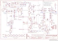
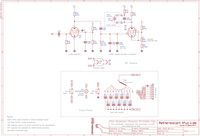
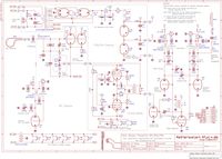
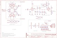
Rockmore- and Rosen Tube-Theremin Schematics
Two Theremin schematics have been prepared, reflecting the known circuitry of the Rockmore [3], [4] and Rosen [5], [6] Theremin instruments. There are many component values unknown. The pitch indicator circuit is totally unknown, except a vague description in Lucie Rosen's Theremin Notebook [6]. This circuit has been reconstructed. Based at the available documentation, plausible component values have been added and corrections introduced. These values are enclosed in rectangular brackets.
The functional groups of the Rockmore and Rosen Theremin circuit are described in more detail next.
Pitch RF-Oscillators
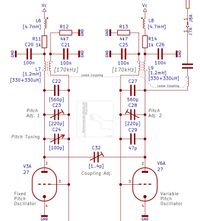
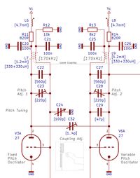
Two Hartley type radio frequency (RF) oscillators ([47] figure 9.17 ‘Dreipunktschaltung mit Reihenspeisung – Three point circuit applying series-supply’ / [37] chapter 21 ‘Die praktische Ausführung der Armstrong-Schaltung – The practical implementation of the Armstrong circuit’, figure 25) utilizing 27' triode tubes [66], generate sine-signals of approx. 170kHz slightly differing from each other; one frequency controlled by the variable impedance formed by the pitch-antenna in conjunction with its extension coil, one fixed. Both apply virtually center tapped parallel resonance circuits witch can be frequency-adjusted via variable capacitors.
Rockmore-Theremin Pitch Oscillators Schematic | Rosen-Theremin Pitch Oscillators Schematic |
The two coupled partial windings of the oscillator coil are connected and grounded for RF via capacitors at the virtual common midpoint. A steady negative DC offset is inherent to the RF signals, which is additionally generated by the two pitch oscillator circuits self balancing via grid-current ([45] chapter 12 ‘Amplituden-begrenzung durch Gitterstrom – Amplitude limitation via grid-current’). The negative voltage is developed at the resistor and filter capacitor at the RF cold connection of the oscillator tank grid-side partial winding. Due to the oscillator 27' tube's control grid acting like a diode, whose anode (plate) is connected to the RF hot side of the winding, the tube’s cathode is equally to the diode’s cathode resting at ground potential. During the positive peaks of the developed RF voltage, this diode conducts; thus a rectified RF current (grid-current) flows through the mentioned resistor producing a negative voltage across the resistor/capacitor combination. Rising negative voltage leads to lower conduction of the tube and therefore to a smaller RF swing; due to this, the rectified voltage decreases according to the time consonant of the grid’s RC circuit, leading to an increase of RF voltage once again. When the time constant is sufficient, this forms a closed loop system which independently stabilizes the RF amplitude. It should be noted that the time constant of the RC circuit should not be made to long (e.g. by increasing the grid resistor) because this would lead to awkward (low frequency) oscillations besides the intended RF signal [6] (sort of super-regenerative action as applied in equally named RF receivers, where a RF LC resonator’s damping is diminished by periodically switching it close to oscillation - usually by an additionally generated frequency somewhat above the hearing-range).
The 27’ tube’s anode (plate) is connected via the second partial winding of the oscillator tank to its supply-voltage (+80V at the tube’s anode/plate) which is filtered by an RLC circuit consisting of a grounded capacitor and an RF choke with series resistor (additionally reducing the quality-factor of the choke for suppressing self oscillations and providing low frequency decoupling), connect to the stabilized +90V supply voltage rail. As said before, the two partial windings must be seen as a center tapped single coil for RF, with a capacitor in parallel to its outer connections – thus a Hartley oscillator configuration. Due to the separated windings, at the oscillator’s grid resonator part the RF swing offset by the rectified negative voltage is present, which is led to the detector tetrode 24’ tube. At the 27’ anode (plate) resonator part, the RF voltage which is of opposite phase to the grid partial winding signal and offset by the positive supply-voltage is available for feeding the antenna resonance-circuit (via a DC blocking capacitor). In Leon Theremin's early designs, the antenna circuit was connected to the grid of the oscillator tube which made the oscillator more sensible to external disturbance signals because they were directly amplified by the tube. Injected RF disturbance signals are less perturbing, when the anode (plate) of the oscillator is used for antenna-circuit connection. The remaining disturbance signals can be effectively reduced by (phase-) compensation effects arising from the small amount of coupling between the two coils of the oscillators. Usually the disturbances are minimized when the coils are oriented for the most pleasing Theremin sound.
Speaking of disturbances, there is another signal which is picked-up capacitive by the antenna and inductive by all coils of the Theremin: the mains hum. Mains hum currents picked-up by the antenna-circuit can be reduced by introducing a high pass filter of sufficiently limiting frequency. This filter as applied in Leon Theremin’s design consist of the relatively small antenna-circuit DC blocking capacitor which has a high impedance for the mains frequency signal and the oscillator tank itself in conjunction wit the connected anode filter circuit, possessing a low impedance for the 60Hz (US) or 50Hz (Europe) mains hum. It is not advisable to connect ungrounded high impedance Theremin oscillator-circuits directly to antennas because this inevitably leads to nasty mains hum (AM- and FM) modulation effects of the Theremin sound.
The coils of the pitch oscillators are wound side-by-side on a single former at the Rockmore/Rosen theremins [6] in contrast to the RCA design [2] where the windings are situated on top of each other. The side-by-side arrangement has the advantage of low additional capacity between the two partial windings – supporting higher pitch sensitivity, but due to the large mechanical separation of the air-core coil, the leakage inductance is very high. Depending on the oscillator working point and the applied tube characteristics, additional RF oscillations, in the order of ten-times the oscillator frequency comprising only small amplitudes, can occur during the positive half-wave of the RF swing. Because these additional oscillations have only fractions of the main RF voltage swing, there’s no notable effect to the Theremin sound quality. It is even unlikely of the additional frequency to be radiated effectively by the antenna circuit because it is tuned to a much lower range and comprises high losses in the higher frequency realm.
Nevertheless, when designing your own Theremin instrument, I would advise to avoid these disturbing oscillations by applying bifilar winding, where the two wires of the coil are wound at once in parallel to each other. This leads to a compensation effect of the inter-winding capacitances because currents with opposite directions flow through the wires. This effect cannot be measured directly using a capacitance measurement device; it would only show the large capacitance between the two closely wound wires. Of course, the wire’s withstand-voltage has to be considered when using bifilar techniques. Because of the close coupling, the leakage inductance is now very small and unwanted high-frequency partial oscillation is unlikely to occur.
Both anodes (plates) of the pitch oscillators are connected by a small value trimmer capacitor (‘coupling trimmer’ [3]). This trimmer in conjunction with the oscillator grid circuits connected to the 24’ phase detector tube and its inter- electrode capacities forms sort of bridge circuit. This bridge is fed by the anode (plate) and grid oscillator RF voltages which are of opposite phase. By the coupling trimmer, the bridge can be adjusted for the desired amount of phase compensation – leading to optimal sound quality and pitch distribution at the lower octaves. This compensation circuit only works sufficiently when the phase relations of all coils are correct, meaning that the mechanical position to each other as well as the general polarity (the coil connections) are set correctly.
One of the RF oscillators is loaded by the antenna resonance circuit which is described in the next chapter. When the hand is removed from the antenna, the load is at its maximum, leading to a minimum bias voltage at the grid RC combination of the oscillator and thus the smallest negative offset of the RF signal at the corresponding 24’ detector tube. In addition, the RF amplitude is slightly lower in this case, even if the tube self regulation as described before is in operation to regain the amplitude. The change of RF and negative offset voltages at the 24’ detector tube while approaching the antenna by the hand alters the pulse-pause ratio of the generated audio pulse signal to some degree and therefore the sound spectrum (pitch dependent sound spectrum).
Pitch Antenna and Extension Coil
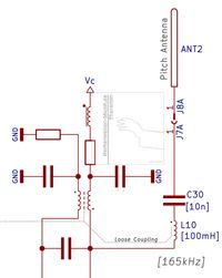
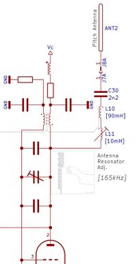
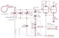
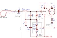
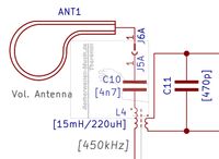
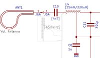
The pitch antenna is connected to the anode (plate) of one RF oscillator via the antenna extension coil to influence the frequency when the hand approaches the antenna. Without the extension coil, the low capacity change of the advanced hand would have just little effect to the RF oscillator in case of the relatively low-impedance resonance-circuits (refer to [47] figure 3.06 ‘Resonanzwiderstand – Resonance Impedance’) used by Leon Theremin [2], [3], [5]. These circuits employ a small value inductance and a large value capacitance (small L/C ratio) to ensure optimal frequency stability. Without extension coil, additional hand capacity at the antenna alone would be way to small in regard to the large capacitor of the oscillator’s resonance circuit to have effect on the generated frequency.
Rockmore-Theremin Pitch Antenna and Extension Coil Schematic | Rosen-Theremin Pitch Pitch Antenna and Extension Coil Schematic |
There have been attempts to omit the extension coil by applying high-impedance resonance circuits in Theremin oscillators already in the 1930’s, refer to [7] and [8] ‘Das Theremin Musikgerät – The Theremin music-device’. To achieve this, in contrast to the low-impedance circuit, a large coil and a small capacitor have been used (large L/C ratio). In some cases, the capacitor was omitted entirely and the self-capacitance of the coil in conjunction with the antenna capacity was applied for optimal sensitivity to define the oscillator frequency.
The general use of antenna extension coils in RF engineering is to match e.g. an RF oscillator to an antenna which is mechanically short and does not provide e.g. the quarter wavelength of the intended RF signal (which is necessary for optimum antenna current and RF radiation). At the Theremin instrument, the antenna extension coil is introduced to extend the antenna influence to the oscillator frequency (which usually has to be prohibited in RF engineering) and form a more linear Theremin pitch field (therefore the extension coil is often denoted as linearization coil) – it does not provide exact tuning of the antenna to the oscillator frequency. At the Theremin, the antenna tuning is only close to the oscillator frequency; thus there are only fractions of the available RF power, as provided by the oscillator, radiated by the antenna.
The extension coil forms a series resonance circuit in conjunction with the antenna capacity (actually the capacity formed by the antenna rod to ground – or the grounded hand), resonating around 170kHz. It produces a high RF antenna current flow at – and even near resonance (low antenna circuit impedance). Due to the small antenna capacity to ground (or the virtually grounded hand), the extension coil must have a high inductance leading to a large L/C ratio [2]. In addition, the coil also must have extremely low distributed parallel capacity - fractions of a pico-farad (pF) to not override the small antenna capacity and a sufficient quality factor (Q) to achieve the desired resonance-curve in conjunction with the series antenna capacity to provide correct pitch linearization. Low distributed parallel capacity means high self resonance frequency (SFR). The coil and its distributed parallel capacity (caused e.g. by windings and connections) form a parallel resonance circuit itself. To not affect the circuit operation, the SFR must be kept as high as possible and outside of the desired working range.
The effects and calculations of inductors like SFR are quite complex and controversial because different theories can be applied, e.g. the wire of the coil can be regarded as transmission-line. Nevertheless, the lumped capacity between the windings and connections of the extension coil must be kept as low as possible, which at Leon Theremin’s designs is achieved by the well known long single-layer air-core coils featuring large diameter bobbins with the antenna arranged at the top. The large cross-section of these coils leads to a sufficiently high quality factor which rises with increased diameter.
A large L/C ratio also means that a great raise in voltage at the antenna is achieved (much higher than the voltage the oscillator is sourcing to the antenna circuit) – a inherent effect of the large L/C ratio, where at each of the components (C and L) of the series-resonance-circuit much higher voltages occur as at the series circuit as a whole. A high antenna voltage is beneficial to achieve a high signal to noise ratio (S/N) in regard to surrounding radio-broadcast and e.g. switch-mode power supply disturbance-signals which enter the antenna as well. In addition, because of the Theremin player is usually wearing shoes while standing on a non conductive floor, the series impedance formed by the player’s body, shoes and the floor to ground, even if the skin effect (RF current mainly flows at surfaces) is taken into account, is high (neglecting the capacitive effects of hand and body to the grounded Theremin circuitry itself). This means that a sufficiently large RF current through ground via all these series impedance obstacles for controlling the oscillator frequency is only possible with a large voltage swing at the antenna.
The formed pitch antenna resonance circuit is strongly coupled to the oscillator’s parallel resonance circuit via connection by a DC blocking capacitor to the anode (plate) of the 27' oscillator tube. These two coupled resonance circuits now influence each other in the intended way that an decrease in (inductive) antenna current lowers the oscillator frequency. This will now be explained in more detail:
With the hand far away from the antenna, its resonance circuit frequency is close to the oscillator’s frequency but slightly lower [2], [6], causing inductive antenna current and therefore the antenna circuit’s influence to the oscillator and it's frequency to be at maximum. When the hand approaches the antenna, the antenna capacity to ground is increased, lowering the antenna resonance circuit frequency. The difference to the oscillator’s frequency expands, the inductive antenna current decreases and thus the oscillator frequency is lowered because the loading by the inductive antenna current is reduced. This current flow through the anode (plate) sided partial winding of the oscillator coil to RF ground acts like a virtual parallel inductance to one half of the oscillator’s parallel resonance circuit, leading virtually to a smaller overall inductance of it.
When the hand is very close to the antenna, the current can become zero; advancing the hand further makes the current rise again but with capacitive phase. Touching the antenna also leads to capacitive current flow.
The effects of the coupled resonance circuits feeding back to each other define the resulting oscillator frequency. Similar effects (influencing the oscillator frequency by inducing phase shifted currents to resonance circuits) are described in [48] p. 295 ‘Die Reaktanzröhre – The Reactance Tube’.
In short: the oscillator frequency (higher) is actually released from the overriding antenna series resonance circuit frequency as the hand approaches the antenna and the oscillator tempts to re-adopt the natural frequency (lower), defined by its own parallel resonant circuit.
This is the case as used in the Theremin instrument, when the oscillator frequency is sufficiently higher than the antenna resonance circuit frequency – the series resonance circuit acting inductively. If both frequencies are to close, a frequency jump to the lower antenna resonance circuit frequency will occur, overriding the oscillator circuit resonance frequency nearly completely [6]. These effect is described in [38] chapter 9-1-G ‘Die Zieherscheinung – The Pulling-Effect’ and [45] chapter 11 ‘Gleichzeitige Erregung mehrerer Frequenzen, Frequenzsprünge – Simultaneous excitement of multiple frequencies, frequency jumps’. Frequency jumps must be prevented for correct theremin function. It is possible that in normal theremin operation this jump does not occur (it does occur especially when the hand is as far away from the antenna as possible in conjunction with high pitch antenna sensitivity), but when the instrument is switched off and back on, the jump occurs – generally leading to a very high audio note. Due to this, the sensitivity of the pitch antenna shall not be set to high, meaning the frequency of the influenced oscillator must stay well above the antenna resonance circuit frequency under all conditions.
Why 170kHz ? The long-wave frequencies were used in the early days of AM radio. Long wave (LW) is and was never a common radio-band in the US but in Europe. This LW radio-band frequency was somewhat reserved back then because it was used as intermediate frequency IF (IF 175kHz [62] p.580, [63] p. 107, [77] p. 1361 ), too; thus there were no powerful stations transmitting there which could have perturbed the Theremin instrument.
The IF is used in superhet-receivers, refer to [77] ch. 26 p.1020 and ch. 35 p.1228.
According to [77] p.1361, common intermediate frequencies were 175kHz, 260kHz, 415..490kHz and 510..525kHz. In Europe, usually frequencies around 460kHz, 470kHz and at the very early receivers 110kHz was used as IF. The EW-Theremin uses frequencies around 260kHz (pitch oscillators) and 455kHz (volume oscillator).
Pitch Phase Detector
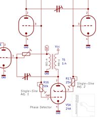
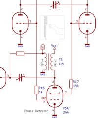
The 24A' tetrode [66] acts as phase detector. It synthesizes the audible difference frequency of the two pitch oscillator RF frequencies. The tube is largely biased negative by the steady DC offset additionally generated by the two pitch oscillator circuits and therefore mainly not conducting. Due to the tetrode’s control-grid to screen-grid capacity, beating of the RF signals, which are connected to the grids, is obtained.
Rockmore-Theremin Pitch Phase Detector Schematic |
Rosen-Theremin Pitch Phase Detector Schematic |
Normally, the RF signals are slightly different in frequency (the fixed oscillator signal is higher by the amount of pitch frequency in regard to the variable oscillator) and the phase cycles as long as the variable oscillator’s frequency difference is large enough for them to not get locked. Locking of the oscillators means that one oscillator synchronizes the other thus both oscillate with identical phase and frequency. Usually the oscillator with the weaker amplitude is synchronized by the stronger oscillator signal.
The phase detector action of the 24A' as used in Theremin designs must not be confused with a multiplicative or additive mixer tube behavior as used in superheterodyne AM receivers. The multiplicative mixing principle is based on the true distortion-free multiplication of two signals with different frequencies. No (or at least only few) additional harmonics are produced – giving a pure output of both input frequencies as well as the sum- and difference of them. In contrast to this harmonic free behavior, an additive mixing circuit (e.g. two RF input signals are merged by capacitors and lead to a non linear device like a triode tube or even a simple diode), outputs both input frequencies, the sum- and difference of them and lots of additional harmonics, including those which originate from re-mixing the output signal.
In principle, the 24A' circuit can be regarded as additive mixer, usually this would be the case when at least one low amplitude RF signal would be applied. At the Theremin application of the circuit, both grids of the tetrode tube are supplied by the large oscillator RF voltages and a negative DC offset. The oscillators provide voltage swings of up to 160Vpp, which are somewhat reduced via the series resistors of the detector tube grids while drawing grid-current. In addition, the tube is cut off completely during RF signals of negative direction. Therefore, the 24A' tetrode tube in the circuit design of Leon Theremin is suggested to be denoted as phase detector and not as (additive-) mixer.
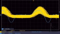
The phase variation of the two RF signals connected via series resistors to the control- and screen grid of the 24A' tetrode, result in an RF burst current (consisting of phase dependent current needle pulses) witch flows through the first interstage transformer connected to the anode (plate), which integrates it.
Ch.1 (yellow): Anode (plate) current of phase-detector tube (6SH2P tube Theremin measurement)
Ch.2 (blue): AF Output voltage of phase-detector stage (6SH2P tube Theremin measurement)
The behavior of this arrangement is somewhat similar to the principle of the EQ80/6BE7 or 6BN6 tube, intended for frequency modulation (FM) detection ([49] p. 163 ‘EQ80’), which only conducts while the two RF signals are in positive direction, widely independent of the input voltages at the control grids. The difference is that the 24A' is not designed for equal grid cut off control and limiter action. This leads to needle current pulses of amplitudes varying according to the phase dependent instantaneous amplitudes of the grid voltages. In addition, there remains a small amount of residual RF current during the burst pause.
The beating RF signal as present at each detector tube grid consists of the large RF amplitude of the accompanying oscillator and a small residual phase varying RF signal of the opposite oscillator, coupled capacitive between the tube grids. This leads to only a small amount of AM like amplitude variation, carried by the large RF oscillator signal connected to the phase detector grids. In contrast, at the detector stage of the Moog Etherwave Theremin, a large AM modulated like half-wave RF beating signal is generated by additive mixing and direct demodulation.
An RF beating signal cannot be denoted as simple AM modulated RF signal. AM modulation means that a single RF carrier’s amplitude fluctuates according to a modulating (low-frequency LF) signal – in general meaning multiplication and generation of a new signal, the AM modulated RF carrier, including side-bands (three resulting frequencies – carrier and two side bands). LF is of course not present in the modulated RF signal directly; the LF signal can only be retrieved by demodulation. Beating of RF signals occurs by linear addition of two RF signals, generating no new AM modulated RF carrier and no side-bands (two ‘resulting’ frequencies – the two originating frequencies); it is therefore no (AM) modulation, refer to [65], chapter 056 ‘Die Spektren der gebraeuchlichen Modulationsverfahren – The Spectra of common Modulation-Techniques’. As mentioned before, at the mixer/detector stage of the Moog Etherwave Theremin, additive mixing of the RF beating signal is performed by a (nonlinear) diode, which performs the mixing- and demodulation action at once.
In Leon Theremins design, the phase detector 24A’ tube only conducts when both grids are simultaneously loaded with sufficiently high positive RF half-waves due to the steady negative biasing. Thus the small AM like amplitude variation has only little effect on the audio frequency (AF) signal to be detected.
The single-sine AF signal which can be measured at the secondary of the first interstage transformer is caused by the detector tubes RF burst anode (plate) current through the primary winding (upper half wave) and the mutual induction effect (lower half wave). This burst current depends on the coincidence of the RF voltages at the tubes grids (phase detector action).
The RF voltages at the grids of the detector tube act in the following way: when we presume the fixed oscillator signal as constant phase- and frequency reference and the signal of the variable oscillator having a stable frequency difference to the fixed oscillator, its phase is constantly cycling in regard to the reference signal phase with the period of the frequency difference between both oscillators. This leads to current flow in the detector tube when both RF signals are of, or almost equal phase and positive polarity. In addition, grid current occurs, distorting the RF signals thus producing harmonics. Among other effects, the amount of grid current can be adjusted by the resistors placed in series to the detector tube grids. The phase cycling of the two beating RF signals is usually not regularly sinusoidal. The phase behavior and therefore the detected RF burst current envelope shape depends upon the coupling between the two oscillators. It can be influenced by positioning the oscillator coils to each other and to the antenna extension coil as well. By doing this, the width and pause of the detected RF anode (plate) current flow envelope and thus the AF signal pulse pause ratio can be adjusted to give a pleasing sound; a sort of pulse width modulation (PWM). The RF burst current envelope is somewhat half-sine shaped.
The first interstage-transformer, connected from the anode (plate) of the 24A' to the high stabilized supply voltage (+180V), integrates this anode (plate) RF-burst current. Due to the inductive integration and the lumped/distributed transformer capacity, the RF signal is no longer inherent to the single-sine shaped audio (pitch) signal at the secondary of the transformer.
Due to the swept negative resistance of the tetrode tube, at a certain working point, determined by the tube's grids and anode (plate) voltages, Dynatron like behavior can occur. The circuit then tends to resonate via mainly the large secondary inductance of the interstage-transformer and it's lumped capacity as parallel L/C resonator. Continuous oscillation is usually prevented by damping via the low quality factor of the audio-interstage transformer itself as well as by the following audio-limiter amplifier 27' tube circuit drawing grid current. Grid current of this tube only occurs at potions of the positive single-sine audio halve wave.
Pitch AF Limiter Amplifier
The 27' triode audio limiter and voltage controlled amplifier tube's control grid is connected to the first interstage transformer's secondary via a resistor which determines the initial damping of the transformer acting as LC parallel resonator at the peak of the positive half-wave when the tube is drawing grid-current. Grid and cathode of the tube form a diode, conducting at positive voltage swings. Therefore, damping is only applied at the positive half-wave, causing the single-sine like audio pulse to be clipped to some extend at the positive portion. The height of the anode voltage of the 27' audio tube determines it's amplification and limiting action. It additionally alters the pulse-pause ratio of the generated audio pulse signal to some degree and therefore the sound spectrum (volume dependent sound spectrum).
Rockmore-Theremin Pitch AF Limiter Amplifier Schematic |
Rosen-Theremin Pitch AF Limiter Amplifier Schematic |
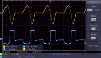
The circuit acts as an non-linear voltage controlled amplifier and limiter, producing an audio signal containing positive and negative directed nearly rectangular shaped have-waves of unsymmetrical duration and amplitude; the limited single-sine signal.
Ch.1: Single-sine audio signal @ secondary of first interstage-transformer; phase-detector output (6SH2P tube Theremin measurement)
Ch.2: Limited single-sine audio signal @ output of limiter-amplifier (6SH2P tube Theremin measurement)
The upper (positive) portion of the single-sine pulse cause the 27’ tube to draw grid current and therefore to conduct excessively (in fact to draw high anode current). The output sound signal at the tube’s anode (plate) becomes therefore mainly rectangular shaped with round corners at the lower part. The large negative potion causes the tube to cut off; this can be noted as fast rising edges at the upper part which becomes rectangular shaped.
It is important that the audio signal shape (at least its pulse width) is slightly volume dependent. The pulse length and amplitude relation of each rectangular half-wave in relation to the pulse-pause duration (the resulting pulse-pause ratio) mainly determines the sound spectrum and therefore the sound impression of the Theremin instrument.
Volume Detector
The volume detector circuit consists of a 53’ [66] dual triode. Both triodes are connected in parallel to achieve higher mutual conductance than of one single triode alone. This is beneficial to give sharp rise and fall of the limiter amplifier’s control voltage for staccato playing. The anode (plate) is connected to the high stabilized positive supply voltage (+180V). The grids are connected to an adjustable parallel resonance LC circuit – the volume detector resonance tank. The resonance frequency and therefore the volume response can be adjusted via the main adjustable capacitor (denoted ‘Vol. Tuning’ in [3]) which is assumed to be accessible by the wooden wheel slightly below the volume antenna and an additional parallel trimmer capacitor.
Rockmore-Theremin Volume Detector Schematic |
Rosen-Theremin Volume Detector Schematic |
To adjust the amount of coupling to the volume antenna extension coil, the resonator coil is wound on a coil-former which is slid over the large extension coil. It can be moved from the cold end, which is connected to the oscillator, to the middle of the extension-coil. The coupling is enlarged when arranging the volume detector resonance coil closer to the middle of the extension-coil, thus increasing detected amplitude and resonator bandwidth, reducing sensitivity and attack of volume response. Moving the detector coil closer to the end of the extension-coil (diminishing coupling) provides somewhat less resonance voltage swing at the detector's parallel tank, but gives smaller bandwidth, leading to higher volume and attack response sensitivity. It must be noted that the attack response, which is essential for staccato playing, is determined by the detector's resonance circuit bandwidth. The LC circuit tends to ring according to its bandwidth; thus it will produce over- and under shoot in the envelope of the RF voltage to be detected at fast varying frequency changes caused by fast hand movements near the volume antenna. The over- and under shoot leads to sharper rising and falling amplifier control voltages, even when the detector-bandwidth is quite small – but a certain small delay is added. For sharp attack, the volume hand has to be moved near the antenna quickly in little advance of the sound to be heard or reduced; a Theremin player gets used to it pretty quickly. Slow movements of the player‘s volume control hand do not produce any additional attack- or decay effects; the volume rises and decreases according to the hand movements. The detector circuit is in fact of the cathode-detector type. Without or with only small RF signal at the parallel resonance-circuit (volume oscillator frequency lower than the resonator’s frequency - while hand is close to antenna), the tube bias is entirely defined by the negative voltage of the ‘detector negative bias battery’ connected from the tube’s cathode to the control-grid via the resonator tank, shutting the tube off. Thus there is no voltage developed across the large resistor which is connected from the cathode to ground.
The Mute switch is connected in parallel to this resistor, to shorten the generated positive volume control voltage to ground for the instrument to become silent (when the hand is removed from the volume antenna and the tube therefore conducts, the tube has to dissipate the full anode/plate power caused by the current of the cathode shorted to ground). When removing the hand from the volume antenna, the oscillator frequency rises and so does the RF swing of the detector resonance circuit according to its adjusted resonance curve. This developing RF voltage leads to the tube conducting if the RF amplitude rises above the cut of voltage as defined by the bias battery, according to its parallelized triode characteristics. This produces the positive control voltage for the limiter amplifier stage, developed across the detector-tube’s cathode resistor.
According to [5] and [6], an additional capacitor is placed in parallel to the cathode resistor, introducing an additional time constant besides removing residual RF, reducing knocking effects caused by too fast hand movements. An additional battery is placed in series from the detector tube’s cathode (carrying the detected positive volume control voltage) to the second interstage transformer of the volume control limiter amplifier circuit. When there’s no or only very small positive detected voltage present at the detector tube’s cathode, this ‘limiter amp. cut off battery’ provides a negative voltage supplied to the anode (plate) of the 27’ limiter amplifier tube. The cathode of this tube is grounded and the grid is supplied by the large positive and negative voltage swing of the single-sine audio signal. Electrons leaving the cathode are being accelerated towards the anode (plate) by the positive portions of the audio signal at the grid. Even if the anode (plate) of the tube would be zero, a residual audio signal emerging from the loaded grid would be present at the connected second interstage-transformer, caused by e.g. inter-electrode capacities and leakage currents due to residual electrons reaching the anode (plate). These effects are greatly reduced by the negative voltage at the anode (plate), forcing the accelerated electrons to return to the control grid, thus not affecting the anode (plate) of the tube any more. The instrument is therefore sufficiently silent at volume cut off. Required is of course the proper wiring of the limiter amplifier stage; audio signal coupling via parallel mechanical arranged wires and components has to be avoided (it can be necessary to ad additional screening). In addition, RF coupling to the audio stages has to be prohibited as well, because e.g. residual RF of the pitch oscillators can be demodulated by the audio tubes, leading to unwanted ghost tones, even if the instrument is muted. Same for proper decoupling of all supply-voltages and grounding.
Volume Oscillator
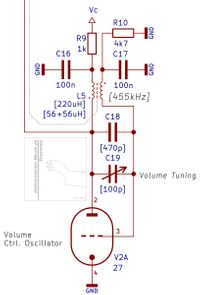
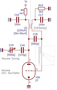
The volume oscillator circuit arrangement is identical to those of the pitch oscillators, despite the component values, optimized for operation around 455kHz.
Rockmore-Theremin Volume Oscillator Schematic |
Rosen-Theremin Volume Oscillator Schematic |
Volume Antenna and Extension Coil
The volume antenna extension coil arrangement is identical to those of the pitch extension coil, despite the component values, being optimized for operation around 455kHz.
Rockmore-Theremin Volume Antenna and Extension Coil Schematic |
Rosen-Theremin Volume Antenna and Extension Coil Schematic |
Why 455kHz ? This frequency represents the common intermediate frequency used in AM receivers ([63] p. 107). It is outside the radio (AM-) band; thus there are no powerful stations transmitting which could perturb the Theremin instrument.
AF Power Amplifier (PA)
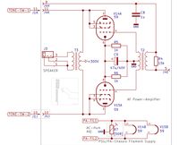
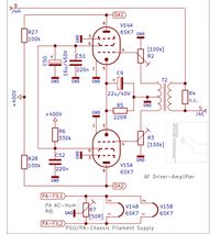
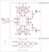
The AF power amplifier applies two 59’ tubes [66] in triode push-pull configuration at the Rockmore instrument, providing up to 15W of audio power. At the Rosen power-amplifier, two 6SK7 pentode tubes in the driver stage and four (!) 6L6 beam power tetrode tubes in push-pull configuration are used, providing up to 100W (!) of audio power.
Rockmore-Theremin AF Power Amplifier (PA) Schematic | |
Rosen-Theremin AF Driver and Power Amplifier (PA) Schematic |
At the Rockmore amplifier, the voltage controlled limiter amplifier 27’ tube’s anode (plate) is connected to the control voltage (53’ tube cathode) via the second interstage-transformer’s primary. A damping resistor is added in parallel to this winding to flatten the frequency curve of the transformer and reduce over-/undershoot. Each of the two windings of the center-tapped secondary is directly connected to the associated control grid of the 59’ tubes. The tubes are driven by the audio signals in opposite phase, supplied by the interstage transformer. The center-tap is connected to ground, while the cathodes of the tubes are tied together and connected via a RC combination to ground. The value of the associated resistor is chosen to develop the sufficient bias voltage for the tubes while the cathode currents of both tubes flow through it (self-biasing). The associated parallel capacitor is of the electrolytic type to provide a sufficiently high value for appropriate amplification of the lower frequencies. The anodes (plates) of the tubes are connected to the dedicated windings of the center-tapped primary of the AF output-transformer [26]. The center-tap is supplied by the filtered voltage of the high-voltage supply (+300V). A multi-contact-switch provides the possibility to connect various capacitors between the outer connections of the center-tapped primary winding. This circuit serves as low-pass filter (LPF).
In fact, the center-tapped winding with added parallel capacitor represents a damped parallel resonance circuit. Due to the large inductance of the winding, small capacitor values are appropriate to cover the whole audio spectrum to be filtered. Due to the low quality factor of the output transformer, the impedance of the tubes and of the connected speaker, the parallel resonator circuit is largely damped, resulting in LPF action only. The resonator circuit is similar to that of the center-tapped (Hartley) pitch- or volume oscillator tanks. If there would be provided low (capacitive-) coupling from the anodes to the opposite tubes grids, the damping could be reduced and a formant filter-effect be introduced. Push-pull oscillator action would arise from increasing the coupling too much. Another means to reduce damping would be to introduce capacitive coupling between each tube’s anode to grid, forming sort of Huth-Kuehn (Miller) circuit in conjunction with the center tapped input interstage transformer with associated lumped parallel capacitors (loosely coupled resonators at the input and output of the power tubes).
The amplifier of the Rosen Theremin instrument is quite similar except of tetrode tubes in the output stage and additional pre-amplification by pentodes in the driver stage. The audio output power is of course much higher, leading to e.g. a larger output-transformer and changed bias- and screen grid supply circuits. In addition, the amplitudes of the phase inverted input signals are adjustable to assure equal levels at the output-transformer’s primary windings, compensating slightly varying tube characteristics (low distortion).
Both amplifiers do not apply negative feedback. This means the full amplification of the tubes is used to drive the speaker; there exists no decrease in distortion, this is in fact not possible because of the implemented LPF using the output transformer. In addition, the internal resistance of the amplifier is quite high thus the speaker is only marginally damped [25]. This leads to excessive over- and undershoot or ringing of the speaker itself, thus formant coloring of the sound. In today's usually low output resistance amplifiers the speaker is heavily damped, reducing effects to the sound introduced by the speaker.
Speaker
The speaker is an essential part of the Theremin which can not be separated from the instrument it was designed for. It can induce additional effects to the sound, dependent on the construction of the baffle, housing and of course the speaker chassis itself [25], [27], [33]. In fact, besides the speaker’s general high- and low-pass characteristics, it acts as all-pass filter, introducing delay (phase shift) for certain frequencies [24]. In addition, the speaker produces amplitude (inter-) modulation effects, denoted as amplitude-modulation distortion (AMD) and frequency-amplitude distortion (FMD), thus coloring the sound [23].
Pitch Indicator
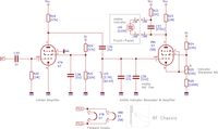
The pitch indicator circuit is not documented by a schematic, only a vague description exists [6]. The circuit function is assumed to be as follows: the detected AF signal of the 24’ phase detector tube’s anode (plate) is amplified by a 57’ pentode tube [66] in the first stage acting as limiter; the screen grid voltage set quite low by appropriate series resistor or voltage divider, the anode resistor quite large, connected to the positive voltage supply rail (+180V). The control grid is loosely coupled to the 24’ anode (plate) via a small capacitor and connected to ground by a large resistor. The second indicator stage applies another 57’ or a 58’ [66] pentode tube. Its anode (plate) is connected via a large resistor in parallel to a neon lamp for resonance indication to the positive supply rail voltage (+180V). The control grid is connected to an AF choke with adjustable parallel capacitor forming a parallel LC circuit. The cathode of the tube is connected to a voltage divider junction, providing sufficient voltage for the tube to nearly cut off when there is only residual audio present while the grid is grounded via the AF resonator choke. The grid resonator circuit is loosely coupled to the first amplifier tube’s anode (plate) to minimize damping, leading to a large voltage swing. The LC circuit resonates at 440Hz, adjustable via the parallel capacitor or the audio-choke by changing it’s inductance L. The choke’s value can possibly be modified by setting the partial pressure of the iron core (air gap distance) at a dedicated screw. The sharpness of indication is dependent on the value of the coupling capacitor at the grid, increasing it pronounces damping (introduced by the first amplifier stage) thus broadening the resonance curve.
Rockmore-Theremin Pitch Indicator Schematic |
Rosen-Theremin Pitch Indicator Schematic |
When reaching the ignition-voltage of the neon indicator, it lights up. This happens at some point when the tube’s anode (plate) current and thus the amplified 440Hz voltage amplitude at the neon indicator rises because of the resonator 440Hz resonance voltage swing applied to the grid overrides the negative bias of the tube, shifting it's working point to larger amplification. The current needed by a neon lamp is usually very small (around 200uA) while the ignition-voltage is quite high (in the order of 100V). Once ignited, the lamp voltage is typically 90V (maintaining voltage). The 440Hz (‘A’) indication action can be adjusted by the voltage divider providing the cathode potential of the tube.
Front-Panel
The Front-Panel holds the Power-Switch, the Power-Indicator-Lamp, the Mute-Switch, the eleven position Tone-Color-Switch (with assembled capacitors) and the Pitch-Indicator-Neon-Lamp. The two rotary knobs for setting the volume (volume-oscillator frequency) and the pitch (pitch-oscillator frequency) are also accessible on the front panel; however, the associated variable capacitors are mounted behind it on the mounting plate that carries the other circuit components and tubes. They are accessible from the front panel via long axes.
| |
Rockmore-Theremin Front-Panel Schematic | Rosen-Theremin Front-Panel Schematic |
Power Supply
The power-supply provides the PA anode (plate) voltage of approx. +300V and regulated voltages (by 2x 874 tubes [66]) of +180V and +90V. At the Rockmore instrument, the AC filament voltage of 2,5V for the 59’ amplifier Radiotron tubes and 5V for the rectifier tube 5U4 are supplied by the main line transformer. The AC filament voltage of 2,5V for the remaining radiotron tubes is supplied by a separate mains transformer.
Rockmore-Theremin Power Supply Schematic |
Rosen-Theremin Power Supply Schematic |
At the Rosen instrument, the AC filament voltage of 2,5V for the Radiotron tubes is supplied by a separate mains transformer, 5V for the rectifier tube 5Z3 and 6V for the 6SK7 and 6L6 tubes are supplied by the main line transformer. The single pole power switch is connected in series to the transformers, which are connected in parallel at their primary windings. There is no mains fuse documented in the schematics [3], [5]. The chassis is connected to mains ground (protection earth - PE), two EMI/RF suppressor capacitors are connected from each of the mains cables to PE.
Tubes
The electron tubes (e.g. Radiotron by RCA [66]) of the 1920s era have many deficiencies like low amplification and non-linearity of characteristic curves. These imperfections are utilized in the circuitry as defined by Leon Theremin. For instance, the trans- or mutual-conductance (mu) of the 27’ triode (RCA UY-227) is typically 0.82mA/V @ 90V and the amplification factor is 9, a ‘modern’ ECC82/12AU7 triode (which has one of the lowest mu and amplification factors at present tubes) provides 3.1mA/V @ 100V and an amplification factor of 19.5.
Especially for TV receiver tuners and IF amplifiers, variable-mu tubes have been developed, mainly intended for RF automatic gain-control (AGC) applications. This was done by varying the (negative-) grid voltage of triode tubes (e.g. PCC189/7ES8 0.9mA/V @ Ug1 -4V) or the screen grid (G2) voltage of pentode tubes like the EF183/6EH7. Pentode tubes with accessible suppressor-grid (G3) can be connected to form a triode or even tetrode. This is very useful in Theremin applications. Of course there do exist many other variable-mu tubes; the advantage of them is that they are cheap, easily available and quite usable in Theremin applications. The reason why they are cheap is of course their inherent non-linearity which leads to distortions and disqualifies them for use in standard audio amplifiers - today's common use for tubes, so nearly nobody will use them. Apart from the audio power amplifier, the Theremin does largely not depend on tubes providing linear characteristics; the oscillators, the phase-detector, the limiter amplifier and even the volume detector perform sort of switching action or non-linear amplification. Hence, these type of tubes are excessively used in the author’s theremin circuits. Tube data can be found in [61], [66] and [49]. General information about tubes and their applications can e.g. be found in [55], [56] and [57] – see literature list.
Coils
The inductors in the Theremin are mainly the antenna extension-coils and the oscillator coils. In Leon Theremin’s instruments, these are of the air-core type. To gain a sufficient quality factor, large diameter coil-formers and thick wires have been used. Nevertheless, the quality factor compared today's inductors is quite low. This has to be taken into account when trying to substitute the large air-core coils by smaller ferrite-core coils in new designs. When using cores with relatively low permeability, the impact of temperature is sufficiently low and the advantage of smaller dimensions predominates. Because the Theremin relies on coupling effects between the coils, screened or capsuled coils are not advantageous when following the original design. Rod ferrite-cores should be used, which can provide sufficient external magnetic fields. For the oscillator-coils, side-by-side winding seems to produce certain interference (as described before). If possible, bifilar-winding techniques should be used. The antenna-extension coils can be wound using long, sectioned coil-formers with internal ferrite core rod. Due to the many sections, the self-capacity can be brought to fractions of a picofarad and thus the SRF made adequately high.
Audio Transformers
The interstage-transformers as used in the early days of radio used to have many deficiencies. The frequency curve of the very early ones e.g. peaked at 1kHz, later transformers had been optimized for the audio-frequency range of AM radio, which usually was up to 4.5kHz. Therefore, those transformers show a quite large level increase at 3kHz to 4kHz with rapidly falls off above these frequencies. Wide-band transformers of the late 1930s were able to capture up to 10kHz (which was called high-quality audio in those days). Due to the AM channel-separation, in Europe a sharp cut-of at 9kHz was usually realized to suppress interference tones generated by adjacent stations. Today, interstage-transformers are uncommon and hard to find. In the original Theremin design, it is necessary to use a appropriate transformer (or at least choke) to produce the single-sine pulse at the phase-detector stage. When the correct induction values for primary- and secondary winding are chosen, small mains transformers can be used alternatively – at least in the customized circuits as tested by the author this was possible without noticeable drawbacks. Of course, when applying transformers without air-gap in circuits without push-pull configuration, the DC loading must be kept as low as possible to not reduce the inductance. Nevertheless, those transformers may be AC coupled using DC blocking capacitors.
Sound Analysis
As said before, the speaker acts mainly as all-pass filter; of course due to its limited bandwidth, high- and low-pass filter effects are involved, too. Dependent on the construction of the speaker chassis and the baffle, it introduces delay (phase shift) and formant behavior for certain frequencies, thus coloring the sound. These effects can be observed when recording the Theremin sound captured in front of the speaker by a microphone (with flat phase- and frequency response) compared to the directly recorded sound of the Theremin power-amplifier output or the voltage controlled limiter amplifier output e.g. displayed at the oscilloscope. Both signal shapes do not have much in common any more. In contrast, when comparing the spectra, there is no essential difference, except of course the high- / low-pass behavior and eventually additional resonance effects of the speaker. There are no known direct recordings (the recording equipment has to be directly connected at least in parallel to the Theremin’s speaker output) of the Rockmore- or Rosen instrument known to be available. Therefore, the signal shape as produced by the instruments at the output is currently unknown.
For comparison only the sound spectra (frequency domain) are appropriate to be analyzed because of the various possible fast changing sound shapes (time domain). Even when there is piano accompaniment in the available recordings, the typical spectrum of the Rockmore Theremin instrument, like a fingerprint, is clearly visible – regardless of how miserable the sound recording quality may be. As said before, recreating the Rockmore sound is a goal of the research. All (re-) build (and simulated) sound creating and influencing circuits have been closely examined in terms of audio spectra similarity to the 'Rockmore' sound.
The objective sound spectra consists of the lower-, mid- and high-pitch segment. The most noticeable (and simple to describe) 'Rockmore-' partial spectrum is the mid-pitch segment. The spectral lines around the frequency of 220Hz are typical arranged in groups as follows:
a) fundamental (220Hz), 2nd, 3rd harmonics almost of equal amplitude
b) 4th harmonic nearly completely suppressed (volume dependent)
c) 5th, 6th, 7th harmonics almost equal of amplitude but lower than at a)
d) 8th harmonic nearly completely suppressed (volume dependent)
e) the spectral line sequence (3 lines -1 suppressed - 3 lines) repeats with declining amplitudes
It must be mentioned, that the audio pulse-width and thus the sound spectrum is volume dependent. With rising volume (especially at very large volume) the suppression of the 4th, 8th and additional harmonics is reduced. This leads to an extended volume impression. This is comparable to the differentiation of whispering and shouting. Even if a whispering sound is amplified and reproduced with much higher volume, it can be still be recognized as a whisper.
The sound spectrum shown in the following pictures is taken from the audio of the well known video ‘Clara Rockmore: The Greatest Theremin Virtuosa‘ by R. Moog, taken in 1976. Clara Rockmore demonstrates the instrument which was build according to her wishes by Leon Theremin. The instrument at that time is assumed to be in perfect order which implies the sound can serve as reference for the analysis of the spectrum.
It must be mentioned that later recordings, e.g. ‘Clara Rockmore’s Gift-Tape’ of 1997 or D. Warshaw playing the instrument in 2010, do not show the described sound pattern any more. I argue that this is not because the sound could only be produced while Clara Rockmore playing this particular instrument – it is much more likely that the noticeable change of the sound spectrum is caused by missing or wrong maintenance (e.g. aging of components, exchange of the vintage 1920s / 1930s tubes by ones produced in the 1940s, providing higher amplification / current capability even when of the same tube type).
When observing this spectrum structure in a sound, it is likely that it equals the Rockmore sound impression. The lower and higher pitches do not show such a clear structure as described above. Several attempts have been made by the author to recreate this target sound spectrum. The simplest way was to closely follow the fundamentals of the original circuitry, generating the single-sine audio pulse with appropriate pulse pause ratio and feeding it to a limiter amplifier; thus creating a dual-rectangular pulse of pitch- and volume dependent asymmetrical amplitude and width. Most important for the spectrum and thus the sound is the pulse width of the large amplitude rectangular shaped signal portion, altering the pulse duration determines if e.g. the 4th / 8th harmonics are sufficiently suppressed and if the spectral amplitudes within a triplet are of appropriate strength.
Frequency dependent pulse-with was also used to electronically create the main sound impressions of wind instruments at the Variophon, a vintage 1980s wind-synthesizer build by the German company REALTON [41]. The general principles of coloring the sound by varying the width and ratio of pulses was already researched by K. E. Schumann in the 1920s [40].
L. D. Korolyov also described the conversion of the detected audio signal to rectangular pulses and the application of formant filter techniques for creation of timbres [70] (L. D. Korolyov: ‘Modern theremin’ Radio, 1985 No. 2 & 1985 No. 3 / Л. Д. Королёв: ‘Современный терменвокс’ Радио, №2 1985г. и №3 1985г).
Even R. Moog used the detected full-wave-rectified like wave-form to create rectangular pulses for further sound processing in his Model 351 tube based instrument [71] (R. Moog: ‘Music from Electrons’, Audiocraft, Audiocom Inc. Great Barrington Mass. USA, No.8 June 1956).
It is not known if the pulse width changed while varying the pitch to create a pleasing sound over the whole range in these instruments of Korolyov and Moog. It can be supposed that this was not the case because both do not mention the importance of the pulse-pause ratio, determining the sound spectrum and thus the timbre of the Theremin instrument. It seems that the main impact to the sound was achieved by filtering the wave-forms, which had been created via complex circuits from the detected source audio signal.
In the EW Standard Theremin of R. Moog, the limiting of the detected full-wave-rectified like wave-form to create rectangular pulses is possible, if the waveform and brightness knobs are set accordingly. Nevertheless, a pleasing sound can not be achieved, because the pulse-width is not sufficient and can not be adjusted. How to modify the EW-Theremin for the pleasing Rockmore-like sound is described by the author at EW Standard Theremin Modifications: EW Standard Theremin ‘Rockmore-Sound’ Modification .
Speaking of the timbre spectrum, now a few words about the sound of the RCA Theremin. The RCA Theremin was manufactured in 1928/29, applying the components used at the Radiola 60 radio receiver. The RCA Theremin was manufactured in parallel to reduce cost. According to the RCA advertisement the Radiola 60 featured ‘wonderful musical range and tone fidelity’. The RCA Radiola 106 dynamic speaker, according to the RCA advertisement [72] a ‘incomparable reproducing instrument of amazing range and tone’, had been advised to be used with the RCA theremin. It must be noted that the speaker included the audio power transformer, not the radio-set or Theremin instrument. Within the Radiola 60 as well as in the RCA Theremin, audio interstage transformers had been used to connect the audio amplification stages to boost the amplification factor. At that time, only low amplification triode tubes have been common, so the interstage transformers have been excessively applied to achieve higher amplification with fewer tubes; this had of course a drawback: limited frequency response. The response peaked typically around 1kHz (this was expanded to 4kHz and later to 9kHz). The frequency response of the early interstage transformers was extremely limited, because of the large distributed capacities of the windings, which had large inductance to match the tube characteristics and provide high voltage conversion ratio.
At that time, this sound quality of low upper bandwidth was sufficient enough, because noise and effects of audio distortion were reduced, while resonating effects were introduced, amplifying additional timbres (which might have been introduced by the distortion of the tubes). The early broadcast stations only transmitted a audio frequency range of 200Hz to 2.5kHz [73].
So what does this mean to the RCA Theremin sound? From the available early recordings of the RCA Theremin, strong formants can be noted in the timbre of the instrument. This is the effect of the interstage- and speaker output transformers, ringing at certain frequencies which are multiplies of about 1kHz, excited by the mainly rectangular audio-wave at the output of the limiter amplifier tube. In addition, the imperfections of the RCA 106 speaker have a non neglect-able influence to the sound quality of the instrument, too. If e.g. the interstage transformers of the RCA Theremin would be exchanged by modern (broadband) types, the timbre will change dramatically because the formant filtering effects of the transformers will be omitted. So, if an original transformer has to be replaced and the sound does not show the formant effects any more, it may help to add at least certain capacitance to the high-impedance secondary winding to achieve ringing around 1kHz.
Conclusion
As can be seen, the circuit arrangement is dependent on the component values / working points and especially on the lumped components.
When closely following the essential principles as applied by Leon Theremin for designing the Rockmore/Rosen Theremins, similar performing instruments of equal sound quality can be constructed, even when using different components.
It must be emphasized that the effects explained here can be observed in the available recordings of Clara Rockmore and are inherent to her instrument as build by Leon Theremin himself.
The circuit parts can not be separated from each other; they work together shaping the sound of the tube Theremin as designed by Leon Theremin in close cooperation with Clara Rockmore and support of Lucy Rosen.

