Rockmorizer Type Theremins
The presented ‘Rockmorizer’ type theremins are based on the original design of Leon Theremin, producing the sound spectrum which is assumed to be close to the instrument of Clara Rockmore. All circuits generate a single-sine audio signal which is formed to rectangular like pulses with appropriate pulse-width to match the desired spectrum.
RT-SILICON-X | RT-6SH2P Tube | RT-6SH2P-X Tube Theremin | FRANZIS Theremin Kit Modification | Rockmorizer Silicon 2017 Theremin |
The RT-SILICON-X Theremin (27.06.2023)
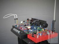
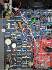
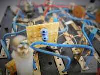
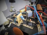
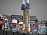
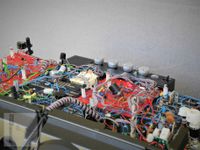
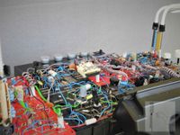
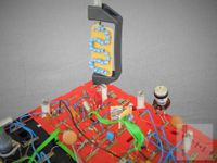
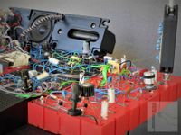
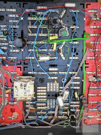
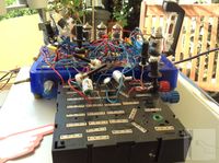
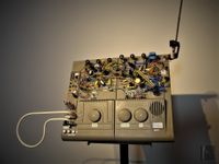
The RT-SILICON-X theremin represents the silicon based version of the RT-6SH2P-X theremin (see below). It was developed to realize the tube based design of LT (Leon Theremin) using standard (silicon) components, no special coils or transformers and only a small speaker of low sensitivity to achieve a sufficient sound quality. As already described at the so called ‘Rockmorizer Theremin’ instruments, the limited single-sine pulse sound spectrum is generated. The RT-SILICON-X theremin enables the player to fully control volume and pitch by the wave of the hands without touching the instrument. A small amplifier to drive a speaker and a simple 440Hz (A) pitch indicator are included. Only a single stabilized DC voltage supply of 15V/1A (wall-wart) is needed externally. The circuit of the experimental setup was realized for testing at a modified Kosmos test-board from March to June 2023.
Listen to the sound of the RT-SILICON-X theremin test-board here (no musical valuable performances):
 | RT-SILICON-X theremin sound 27-05-2023 RT-SILICON-X theremin test-board sound RT-SILICON-X_Test-070_27-05-2023.mp3 (2.63MB) |
RT-SILICON-X theremin test-board sound
| RT-SILICON-X_Test-070_27-05-2023.mp3 (2.63MB) |
| RT-SILICON-X theremin sound 25-06-2023 RT-SILICON-X theremin test-board sound RT-SILICON-X_Z0006_25-06-2023.mp3 (3.73MB) |
RT-SILICON-X theremin test-board sound
| RT-SILICON-X_Z0006_25-06-2023.mp3 (3.73MB) |
RT-SILICON-X Theremin Schematics
The circuit of the RT-SILICON-X theremin as presented in the schematics is discussed below. It represents the 06-2023 version (0v1). More detailed descriptions of the electronic principles used by Leon Theremin in his original designs can be found in the Rockmore/Rosen theremin explanations.
 | RT-SILICON-X Theremin Schematic 0v1 RT-SILICON-X Theremin Schematic RT-SILICON-X_SCH_0v1.pdf (297.77KB) |
RT-SILICON-X Theremin Schematic
| RT-SILICON-X_SCH_0v1.pdf (297.77KB) |
RF & AF Circuit
The RF circuit and parts of the AF circuit are presented at page one of the schematic.
")
PSU-PIU-PA Circuit
The PSU (Power-Supply-Unit), PIU (Pitch-Indicator-Unit) and PA (Power-Amplifier) part of the circuit is presented at page two of the schematic.
")
Circuit Description
The fixed- (Q3) and variable (Q4) pitch radio frequency (RF) oscillators work in Hartley type configuration, utilizing standard low-power / low-frequency NPN silicon transistors (BC546B). They generate sine-signals of approx. 261kHz [297kHz] slightly differing from each other; one frequency controlled by the variable impedance formed by the pitch-antenna ANT2 in conjunction with its extension coil L19 to L46 (L19 to L41), one fixed.

Both oscillators apply virtually center tapped parallel resonance circuits which can be tuned via adjusting the distance of the closely located standard ferrite-core chokes. The working point of each oscillator to produce a stable RF signal (approx. 10Vpp) is determined by the transistor's base voltage divider (R9/R10; R11/R12) and the current setting resistors (R41; R42) at the emitters. The antenna resonator is connected to the collector of the transistor Q4 via DC blocking capacitor C17. The +8V stabilized voltage rail supplies the oscillators via decoupling R/C networks. Due to the large emitter resistor, the oscillator circuit can be regarded as switched voltage controlled current source.

There is no costly mechanical adjustable capacitor included; the pitch can be adjusted at each oscillator by the virtual variable capacitor circuit (phase controlled bridge), build around the symmetrical diode-bridge circuit which applies phase-controlled switching. The phase angle and thus the amount of (mean) capacitive current flow is dependent on the setting of the trimmer R19 / potentiometer R23. When set to high resistance (high RF frequency), the (DC) loading of the bridge is low and thus the rectified voltage across C28 and C30 is high, resulting in diodes mostly non conducting and low capacitive current flow through the capacitors C21/C41 and C23/C42. When set to low resistance (low RF frequency), the (DC) loading of the bridge is high and thus the rectified voltage across C28 and C30 is low, resulting in diodes mostly conducting and high capacitive current flow through the capacitors C21/C41 and C23/C42. The bridge is driven by the symmetrical RF output signals of the oscillator and capacitors C28/C30 effectively act as short for RF, so only little residual asymmetrical RF voltage is present at the bridge trimmer / potentiometer, which is additionally suppressed by the by R/C networks. The pitch can be shifted by about ±2kHz, even though it would be possible to achieve much higher frequency deviation with the circuit.

The critical pitch antenna extension-coil is composed of 27 [22] series connected and inductively coupled standard ferrite-core chokes, each providing sufficient high self-resonance frequency (SRF) and quality factor. This results in very low total distributed capacity and therefore sufficiently high resulting SRF and thus pitch sensitivity. The total inductance can be adjusted by increasing or decreasing the distance of the closely located chokes; it must be matched to the used antenna rod. F type connectors (male / female) with sufficient diameter, as generally used for satellite TV, have been utilized for connecting antenna, extension-coil unit and experimental mounting-plate.

The rod-antenna is mounted on top of the extension coil to reduce additional lumped capacities from the ‘roof’ connection of the coil to ground. In the test arrangement, the antenna consists of an old folding pocket umbrella rod. The surface coated separated aluminum umbrella rod parts had to be partially abraded to made them conductive to each other. The lowest rod is then fixed to the F type connector.
In case of disturbance by radio bacons (NDB) or other services, pitch oscillator and accompanying antenna resonator frequency may be changed applying component values as indicated in [brackets].

The phase-detector applies two standard BC546B low-power / low-frequency NPN silicon transistors (Q7, Q8). The RF signals of the pitch-oscillators are connected to the bases of the transistors via trim-pots for audio-pulse and pitch linearity adjustment as well as for determining the single-sine audio amplitude at the audio-interstage transformer T1. The trimmer capacitor C48 provides additional fine tuning of RF coupling and phase shift. In combination with the RF phase set by the distance and orientation of the oscillator coil-sets to each other, the correct single-sine AF curve is adjusted. T1 is a standard mains transformer, providing sufficient inductance (PRI:35H / SEC:60H). Both transistors only conduct when at least parts of the oscillator signals are of equal phase, resulting in a somewhat half sine shaped envelope of the produced current spikes which flow through the primary of T1 via the B-E diode of transistor Q11 (Limiter) as well as the resistor-capacitor combination R62/C63, supplied by the +12V rail. Q10 in combination with Q11 (refer to [52]) acts as a limiter amplifier stage, converting the integrated RF current pulses of the phase-detector to a rectangular shaped AF signal of constant high amplitude. It is further processed at the pitch-indicator and zero-pitch detector circuits.

The secondary winding of the transformer T1 is connected to the Gate of the voltage controlled AF limiter-amplifier J-FET Q9 (J112). The value of capacitor C55, which might be connected in parallel to the secondary winding if necessary, is selected in conjunction with trim-pot R47 (damping of T1 adjustment) to produce the appropriate audio-waveform while forming a parallel resonance circuit with (mainly) the secondary inductance of T1. When R47 is set to high (low damping; high resistance), there is a lot of overshoot and ringing which can be noted as strong formant in the produced sound. The single-sine pulse is supplied via R48 to the Gate of the limiter-amplifier J-FET Q9. By trim-pot R58, the DC voltage of the Gate with respect to Source can be adjusted to produce a asymmetrically limited audio pulse at the AF output. A additional small voltage, derived from the volume-control detector via potentiometer R26 (Pulse Width), is supplied to the cold secondary connection of the interstage transformer T1, to provide fine-adjustment of the audio pulse-width and thus the sound. This voltage only slightly changes the DC working point of the J-FET Q9.
 Waveform 110Hz |  Waveform 220Hz |  Waveform 440Hz |
BLUE: Interstage Trans. Secondary <T1-6> |
The Drain is connected via R33 and diodes D16 and D17 to the volume-control voltage (CTRL), sourced by the Volume-Control Detector stage (Q1/Q2) described below. In contrast to a tube, the J-FET conducts/amplifies even when the supply voltage is reversed. The applied diodes therefore totally disconnect the audio signal at volume cut-off. In this state, they are biased negative and do not conduct. The additional diode D14 does conduct at sound cut-off to provide low impedance to (virtual) AF ground, resulting in improved suppression of residual audio hum. Switching diode D15 provides means for muting the audio output at Zero-Beat via the zero-pitch detector, described below.
The output signal supplied to the AF power amplifier is additionally low-pass filtered by C50, while C46/C47/R44 form a high-pass filter to sufficiently suppress the control voltage bleed-through.
R40 in combination with the 'Master Volume' potentiometer of the AF power amplifier form a voltage divider considerably reducing the large AF output level. A very small additional audio pulse voltage is added here capacitively via C54 (Hum Comp.) to compensate for residual AF feed-through. C54 may be composed of two short paralleled isolated solid wires with appropriate length and distance. The volume of the audio signal can be adjusted by potentiometer R79 (Master Volume) and the AF amplifier U1 (TDA2003) is used to drive a speaker, both shown at page two of the schematic.

The zero-pitch detector converts the rectangular AF signal (PULSE) of the limiter-amplifier (Q10/Q11) to a DC control-signal (ZPD) for muting the audio output of the volume-control limiter-amplifier (Q9) when no phase-detector output is generated. This effectively suppresses RF interference noise at zero-beat, especially when the controlled limiter amplifier Q9 runs at full amplification (hand removed from volume-control antenna). When there is PULSE signal present, it is rectified by the simple peak-voltage-detector. The generated voltage is negative with respect to the 12V supply rail, generating base-current for PNP transistor Q6. With Q6 conducting, the signal ZPD rises well above the limiter amplifier Q9 control-voltage (CTRL) and switching diode D15 does not conduct; thus the AF signal is not influenced. When there is no PULSE signal present (Zero-Beat), Q6 is shut off, causing the ZPD voltage to fall near or below the source voltage (VIG) of Q9, leading D16, D17 and Q9 to shut of also. R54 of the zero-pitch detector in combination with D15 and R33 of the volume-control limiter-amplifier form a voltage divider; thus there is no hard switching / muting of the audio signal at Zero-Beat. The time constants of the circuit lead to soft fade-in and out above / below approx. 20Hz.

To control the volume of the instrument, a voltage has to be generated which varies according to the hand movement near the volume antenna. Therefore, the volume-oscillator is frequency modulated (FM) according to the hand movement. This signal is then converted to an amplitude-modulated (AM) RF voltage, which is then demodulated, producing the desired volume-control voltage. The needed circuits and their functions, close to Leon Theremin’s design, are described next.
The volume control circuit consists of the frequency variable ‘volume’ radio frequency (RF) oscillator (Q5) in Hartley type configuration (utilizing a standard BC546B low-power / low-frequency NPN silicon transistor) and the Volume Control Detector discussed below. The oscillator applies a virtually center tapped parallel resonance circuit (L11/L12, C18/C25) which can be tuned via adjusting the distance of the closely located standard ferrite-core chokes. It generates a sine-signal of approx. 470kHz. The frequency is controlled by the variable impedance formed by the volume-antenna ANT1 in conjunction with its extension coil (L1 to L10). The working point of the oscillator to produce a stable RF signal (approx. 8Vpp) is determined by the transistor's base voltage divider (R6/R7) and the current setting resistor (R43) at the emitter. The antenna resonator is connected to the collector of the transistor Q5 via DC blocking capacitor C24. The +8V stabilized voltage rail supplies the oscillator via a decoupling R/C network. Due to the large emitter resistor, the oscillator circuit can be regarded as switched voltage controlled current source.

There is no costly mechanical adjustable capacitor included; the volume oscillator frequency can be adjusted by the virtual variable capacitor circuit (phase controlled bridge), build around the symmetrical diode-bridge which applies phase-controlled switching. The phase angle and thus the amount of (mean) capacitive current flow is dependent on the setting of the potentiometer R29. When set to high resistance (high RF frequency), the (DC) loading of the bridge is low and thus the rectified voltage across C40 is high, resulting in diodes mostly non conducting and low capacitive current flow through the capacitors C32/C43. When set to low resistance (low RF frequency), the (DC) loading of the bridge is high and thus the rectified voltage across C40 is low, resulting in diodes mostly conducting and high capacitive current flow through the capacitors C32/C43. The bridge is driven by the symmetrical RF output signals of the oscillator and capacitor C40 effectively acts as short for RF, so only little residual asymmetrical RF voltage is present at the bridge potentiometer, which is additionally suppressed by the by R/C networks. The volume oscillator frequency can be shifted by about ±4kHz, even though it would be possible to achieve much higher frequency deviation with the circuit.

The critical volume-antenna extension-coil (L1 to L10) is composed of 10 series connected and inductively coupled standard ferrite-core chokes, each providing sufficient high self-resonance frequency (SRF) and quality factor. This results in very low total distributed capacity and therefore sufficiently high resulting SRF and thus volume-control sensitivity. The total inductance can be adjusted by increasing or decreasing the distance of the closely located chokes; it must be matched to the used loop antenna. F type connectors (male / female) with sufficient diameter, as generally used for satellite TV, have been utilized for connecting antenna, extension-coil unit and experimental mounting-plate.

The loop-antenna is mounted on top of the extension coil to reduce additional lumped capacities from the ‘roof’ connection of the coil to ground. In the test arrangement, the antenna consists of an curved plastic pipe. Before bending of the pipe, it has to be filled e.g. with sand or salt, using adhesive tape to close the open endings before heating it up by hot air to get flexible. This prevents it from loosing shape while it gets bend around e.g. a tin can of sufficient diameter. Because the antenna has to conduct, e.g. a coax-cable is placed inside the pipe. The outer (!) conductor is then connected to the F type connector.

A portion of the volume-oscillator’s RF pulse signal, present at the Emitter of Q5, is supplied via C33 and trimmer C26 to the virtually center tapped Volume Control Detector parallel resonator circuit. It consists of the series connected, inductively coupled standard RF chokes L13 / L14 and paralleled capacitors C15 / C16. The Base of the Emitter-Detector transistor Q2, utilizing a standard BC546B low-power / low-frequency NPN silicon type, is connected to the virtually tapped inductor (L13, L14) holding the low impedance resonance RF voltage, offset by the bias voltage which is negative in respect to the Emitter of Q2. It is adjustable by R16 (Det. Bias Adj.). The resonator is grounded for RF via C19 and C31. The low impedance connection to the resonator tank is important because Q2's B-E diode draws some RF current due to rectifier action. The NPN/PNP transistor combination of Q1 and Q2 (refer to [52]) represents a circuit which can be regarded as NPN darlington with only one B-E diode junction. Without the virtual tapping, loading of the parallel L/C circuit would broaden the resonance curve and thus reduce the sensitivity of the detector to frequency changes of the oscillator with hand movement. The resonance peak is also influenced in terms of amplitude and bandwidth; when the applied captive coupling by the small trimmer capacitor (C26) is advanced (high value), the resonator voltage increases and the bandwidth increases (wider resonance peak) – this means the circuit gets less sensitive to frequency changes. When the trimmer capacity is reduced, the resonator voltage decreases and the bandwidth decreases (narrower resonance peak), leading to a higher sensitivity to frequency changes. So there has to be found the right setting of resonator coupling, detector bias and antenna / oscillator interaction to achieve the desired volume response. All these variables are of course non-linear and compensate to some extent.
The frequency of the volume-control oscillator changes with the hand movement (FM), and thus the RF amplitude at the resonator varies accordingly (AM). The resonator is tuned to produce somewhat below maximum amplitude at the frequency which corresponds to the hand removed from the volume-antenna. When the hand approaches the antenna, the frequency is lowered and the amplitude decreases. Thus, the simple circuit converts FM to AM. Trim-pot R16 allows to adjust the volume cut-off and response of the instrument in combination with trimmer capacitor C26. A low steady residual RF signal is present at the Base of the detector transistor thus R16 is adjusted to a level where the volume-control voltage at the Emitter of the detector reaches about +3V with the hand approx. 5 to 10cm away from the volume-antenna. Further approaching the antenna lowers the voltage further to about +1V. With increasing frequency, while removing the hand from the volume antenna, the Base of Q2 is loaded with rising RF amplitude (offset by the negative Base voltage with respect to the Emitter developed at R16/R26). This leads to more and more conduction, caused by the positive portions of the RF, shifting the volume-control voltage, developed across C31 (and R16/R26), up to +8V.
The volume ‘knock’ when playing staccato, meaning over- and undershoot of the volume control voltage due to feedback at fast voltage changes, can be adjusted at trimmer R15 (Overshoot). This trimmer changes the amount of low frequency signal which is feedback via the RF cold side of the resonator-coils to the Base of transistor Q2. The low-frequency resonance-frequency is mainly determined by the large capacitors C19, C31 and C34. The effect (ringing) should not be pushed to hard.

The Q1 transistor Emitter voltage (detector transistor combination Q1 / Q2) is supplied via the mute switch, delayed by R8 / R1 and C5 to suppress pop noise while switching. In addition, mute indicator bi-color LED D1 is switched accordingly.
The volume-control voltage (CTRL) supplies the Drain of the voltage controlled limiter amplifier J-FET Q9 and the volume indication instrument M1 (with series connected current limiting resistor R56 and trimmer R52 to set the maximum indication). Diode D18 serves as reversal protection. The large electrolytic capacitor C59 suppresses fast control-voltage transients. When omitting M1, the indicators current loading has to be taken into account. The volume-control voltage (CTRL) ranges from the blocking voltage of +1V to about +8V at full volume, supplied by the Volume Control Detector circuit.

To avoid mains ground-loops, only RF-Grounding (instrument chassis to PE) by paralleled small capacitor and large resistor is applied.

The PSU (Power-Supply-Unit), PIU (Pitch-Indicator-Unit) and PA (Power-Amplifier) part of the circuit is presented at page two of the schematic. The external +15V supply is connected via J3, the (external) speaker is connected at jack J4.

The AF Power-Amplifier (PA) applies the TDA2003 integrated circuit, originally intended for car-radio use. It is supplied from the +15V rail and can deliver up to 3 watts of audio power. It is pretty old but easily available, cheap and can be supplied by a single low supply voltage. This voltage is decoupled by an electrolytic capacitor paralleled by a ceramic capacitor. At the input, the Master-Volume potentiometer in series with the large series resistor reduces the high audio output-level (up to 3Vpp) of the Volume-Control Limiter-Amplifier to an appropriate level. A small capacitor is placed directly at the amplifier’s positive input to suppress residual RF noise. The large output electrolytic capacitor ensures good bass response. A Boucherot cell (or Zobel network), consisting of a capacitor and a small resistor connected in series directly at the amplifiers output, sufficiently suppress possible regeneration / oscillation tendency of the amplifier.
")
In addition to the standard negative feedback, consisting of the voltage divider at the amplifier’s output connected by a large electrolytic capacitor to the negative input, a bridged T-Filter with appropriate DC blocking capacitor and series resistor is placed in parallel. Due to the added filter, a bass-boost (80Hz) and a discant boost (6kHz) is achieved, which is necessary to drive the intended small low efficiency speaker chassis. The negative feedback is therefore frequency dependent; it is reduced around the boosted frequencies, which increases (!) distortions and internal resistance of the amplifier. In addition, it decreases damping of the speaker, pronouncing ringing of the speaker itself.
This behavior is inherent to most of the old time tube radio sets, which mostly use excessive negative feedback circuitry to shape the sound response; in combination with the used high efficiency speakers, this is why these radios are often praised for their unique sound reproduction qualities.
When using a high efficiency sensitive broadband speaker chassis, the feedback component values may be adapted to C78=39n/R80=0R/R82, C82, C83=N.C. (not connected), omitting the bass- and discant-boost. The boosting might be made switchable in future developments.

The 440Hz Pitch-Indicator consists of a simple single transistor low-pass-filter based 440Hz band-pass resonator, rectifier and differential bridge driven bi-color indicator. The large audio -pitch-square-wave signal of constant amplitude, supplied by the limiter circuit, is connected to the input of the 440Hz resonator via a DC blocking capacitor and a large series resistance. Due to the low resistance input DC voltage divider, this leads to a very small initial rectangular AF input voltage of the filter. The center frequency (440Hz) is adjusted by trimmer R70 (Center Frequency). The resonance peak (output voltage amplitude and indicator bandwidth) can be adjusted at trimmer R74 (BP-Quality). It has to be avoided to set excessive high feedback and peak output voltage; the filter will resonate, synchronize and lock to the input frequency for quite a wide pitch range. This behavior must be avoided here for correct 440Hz indication, it is somewhat similar to the well known PLL- or vintage direct-conversion receiver (homodyne, synchrodyne).

The resulting sinusoidal 440Hz signal is rectified by a two diode peak-voltage detector. To drive the bi-color indication LED, the detected voltage is amplified by the left side of the transistor bridge circuit. The left two transistor unit (PNP/NPN; refer to [52]) represents a circuit which can be regarded as PNP darlington with only one B-E diode junction. It features high input impedance to minimize loading of the detector. At the right of the bridge, a single PNP transistor amplifies the reference voltage which is adjusted at R72 (Color Adj.). By the setting of this trimmer, the bi-color LED color is adjusted to only change from green to yellow and finally red when 440Hz pitch is present.

The Power-Supply Unit (PSU) provides the fused, reversal protected, switched and decoupled +15V rail as well as the stabilized +12V and +8V supply. The linear regulators outputs are additionally protected against voltage reversal at power up/down by diodes and apply standard decoupling techniques.
General Notes
To generated the Rockmore like audio spectrum, the correct polarity of the windings of T1 and the oscillator coil-sets is essential (polarity denoted by dots in the schematic). In addition, the correct pulse-pause ratio of the output audio-signal (and the linearity of the pitch range) must be adjusted by rotating the pitch oscillator coil-sets to each other and varying their distance. If the desired sound can not be adjusted, the RF phase relation or transformer polarity may be wrong. It is advisable to test reversing e.g. the secondary of the AF transformer. If this has only minor effect, the phase of one of the oscillators may be reversed by flipping start and end of each of the resonator chokes (denoted by dots in the schematic). Of course, adjustment by rotating the pitch oscillator coil-sets to each other and varying their distance must be repeated.

Because simple fixed RF cokes are used, the total inductance is adjusted by bending the chokes to enlarge or reduce their mechanical distance to each other (decrease or increase the total inductance value).
The component values largely depend on the characteristics of the inductors, antennas and general assembly of the circuit, thus the given values can only serve as guideline.
To adjust the instrument for highest sensitivity, the antenna-extension coils have to be set to max. inductance first (minimum distance of partial chokes). After setting the desired working rest-frequency (hands removed from antennas) by adjusting the distance of the oscillator ferrite chokes, the inductance values of the antenna-extension coils can be reduced (enlarging distance of partial chokes) while re-adjusting the oscillator-frequencies to the previous values. This has to be repeated until the desired antenna sensitivity is reached. When frequency jumps occur during inductor tuning, approaching the hand to the antenna or switching the instrument off and back on, the value of the affected extension coil has to be re-enlarged until no jump occurs any more. It is better to adjust for lower sensitivity (higher values of the extension-coils) to prevent jumps when changing the position or grounding of the instrument. In general, the sensitivity depends on the L/C-ratio of the oscillator tank. The higher the ratio (L value high, C value low), the more sensitive the antenna becomes when the hand approaches it (Theremin instruments omitting antenna-extension coils – which do not correspond to the original design concept- apply a extremely high L/C-ratio to achieve appropriate sensitivity).

The RT-6SH2P / 6ж2п Tube Theremin (09.04.2022)
The RT-6SH2P Tube Theremin applies Russian 6SH2P (6ж2п / 6AS6 / 6J2P) dual-control tubes. These 7-pin tubes draw little filament-power (175mA @ 6.3V) are small, cheap and readily available. Due to their characteristics, they can be used in circuits at low supply voltages.
The RT-6SH2P Tube Theremin is oriented at the original design of Leon Theremin, applied at e.g. the Rockmore / Rosen theremin instruments (refer to Rockmore/Rosen theremin explanations). It is realized for circuit testing at a modified Kosmos test-board which can hold up to five 7-pin miniature tubes; only four are used in the RT-6SH2P circuit. This theremin was designed to test the application of 6SH2P (6ж2п / 6AS6 / 6J2P) tubes for generating the Rockmore sound (limited single-sine pulse sound spectrum). The sound of the 03-2020 version is presented at the accompanying test video.
The objective sound spectrum consists of the lower-, mid- and high-pitch segment. The most noticeable (and simple to describe) partial spectrum is the mid-pitch segment. The spectral lines around the frequency of 220Hz are typical arranged in groups as follows:
a) fundamental (220Hz), 2nd, 3rd harmonics almost of equal amplitude
b) 4th harmonic nearly completely suppressed (volume dependent)
c) 5th, 6th, 7th harmonics almost equal of amplitude but lower than at a)
d) 8th harmonic nearly completely suppressed (volume dependent)
e) the spectral line sequence (3 lines -1 suppressed -3 lines) repeats with declining amplitudes
It must be mentioned, that the audio pulse-width and thus the sound spectrum is volume dependent. With rising volume (especially at very large volume) the suppression of the 4th, 8th and additional harmonics is reduced. This leads to an extended volume impression. This is comparable to the differentiation of whispering and shouting. Even if a whispering sound is amplified and reproduced with much higher volume, it can be still be recognized as a whisper.
The sound spectrum of the RT-6SH2P Tube Theremin is shown below. It is quite similar to the timbre of the instrument of C. Rockmore (spectrum taken from the audio of the video ‘Clara Rockmore: The Greatest Theremin Virtuosa‘ by R. Moog 1976), located on the right for comparison (refer to ‘General Functionality of the Rockmore- and Rosen Instruments').
 |  |
RT-6SH2P Theremin | Rockmore Theremin |
 |  |
RT-6SH2P Theremin | Rockmore Theremin |
 |  |
RT-6SH2P Theremin | Rockmore Theremin |
The circuit of the RT-6SH2P Tube Theremin as presented in the schematic is discussed below. It represents the 06-2020 version revision 0.2. In the new revision, Diode D1 was added to prevent the voltage at electrolytic capacitor C4 from reversing during heating up of the tubes, where the -20V voltage, produced by one of the pitch oscillators, is not present yet. More detailed descriptions of the electronic principles used by Leon Theremin in his designs can be found in the Rockmore/Rosen theremin explanations.
Measurements have been performed at the circuit of the Tube Theremin which can be found at the Messungen/Measurements page.

| RT-6SH2P Tube Theremin Schematic Rev. 0.2 RT-6SH2P Tube Theremin Schematic Rev. 0.2 Download RT-6SH2P_SCH_0v2.pdf (92.19KB) |
RT-6SH2P Tube Theremin Schematic Rev. 0.2 Download
| RT-6SH2P_SCH_0v2.pdf (92.19KB) |
The fixed- (V4) and variable (V3) pitch radio frequency (RF) oscillators work in Hartley type configuration, utilizing the 6SH2P (6ж2п / 6AS6 / 6J2P) tubes in triode configuration. They generate sine-signals of approx. 156kHz (a frequency where only low distortion by RF stations occur at the author’s location) slightly differing from each other; one frequency controlled by the variable impedance formed by the pitch-antenna in conjunction with its extension coil, one fixed. Both apply virtually center tapped parallel resonance circuits which can be frequency-adjusted via variable capacitors and inductors.
The critical antenna-extension coil was wound on a 3D printed multi-section former with adjustable ferrite-core, already designed in 2017. It provides very low distributed capacity and therefore sufficiently high self-resonance frequency (SRF). The rod-antenna is mounted on top of the extension coil to reduce additional lumped capacities from the ‘roof’ connection of the coil to ground.
The phase-detector applies another 6SH2P (6ж2п / 6AS6 / 6J2P) tube V2. The oscillator signals are connected to the control- and suppressor grid via trim-pots (for audio-pulse and pitch linearity adjustment) while the screen grid is supplied by an adjustable voltage affecting the single-sine audio amplitude at the audio-interstage transformer T1 which is connected to the anode (plate) of the tube V2.
The secondary winding of the transformer T1 is connected via trim-pot R10 for pulse width-adjustment of the limited single-sine signal to the voltage controlled AF limiter-amplifier tube V1. The value of capacitor C7, which is connected in parallel to the secondary winding, is selected in conjunction with trim-pot R9 (damping of T1 adjustment) to produce the appropriate audio-waveform while forming a parallel resonance circuit with (mainly) the secondary inductance of T1. The limiter-amplifier 6SH2P (6ж2п / 6AS6) tube’s control grid is grounded because the mutual conductance is too high for correct limiting action. The single-sine pulse is supplied via R10 to the suppressor grid instead. By trim-pot R8, the screen grid voltage of the tube can be adjusted to produce a asymmetrically limited audio pulse at the AF output. The output signal supplied to jack J1 is additionally low-pass filtered and can be adjusted by potentiometer R1 (Main Volume). In the test setting, the M35-AMP amplifier, as described below, was used to drive a speaker.
To simplify the circuit, the RF oscillator, detector and antenna for volume control have been omitted. The volume control voltage is directly derived from the potentiometer RV1. At the test-broad, RV1 is mounted below the multi-point contacts which connect the components. It is controlled by the player via Bowden thread. As can be seen from the schematic, the lower pin of RV1 is connected to trim-pot R4, which allows to adjust the negative cut of voltage. The volume control voltage, supplied from RV1 to the anode (plate) of the voltage controlled limiter amplifier tube V1, can therefore range from approx. the negative cut-off voltage to the supply voltage of +40V. The negative voltage is derived from the fixed pitch oscillator’s self-regulation voltage, residual detected audio is reduced by the large capacitor C4. Diode D1 prevents the voltage at electrolytic capacitor C4 from reversing during heating up of the tubes, where the -20V voltage, produced by one of the pitch oscillators, is not present yet.
The volume ‘punch’ when playing staccato, which is inherent to the original circuits applying volume antenna-extension coil and detector resonator, is not available at the presented circuit. It may be emulated by introducing a appropriately ringing (low-pass) filter, producing over- and undershoot at the volume control voltage (not shown).
The filaments of the tubes are connected in series to be sourced e.g. from the +40V supply voltage via an appropriate 175mA current-source (not shown).
To generated the Rockmore like audio spectrum, the correct polarity of the windings of T1, L1 and L2 is essential. In addition, the correct pulse-pause ratio (refer to the Messungen/Measurements page) of the output audio-signal (and the linearity of the pitch range) must be adjusted by rotating the pitch oscillator coils to each other and varying their distance.
The M35-AMP (25.05.2022)
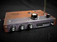
The M35-AMP is a vintage 1970s audio power amplifier construction kit of a previously unknown manufacturer.
The M35, denoted as ‘35W/4Ohms power-amplifier applying darlington transistors’, has now been accidentally discovered in advertisements of ‘Thomsen Elektronik’ at the April 1972 issue of the German radio-electronics magazine ‘Funkschau’ (1972-07) and ‘REEH ELEKTRONIK’ at the February 1973 (1973-03) issue. REEH ELEKTRONIK was a German electronic parts distributor located in Frankfurt a.M. which existed from 1969 to 1977 only, Thomsen – Elektronik GmbH (Greifenstein-Nenderoth, Germany) is in this business too and still exists.
According to the catalog of 1973 [80], courtesy of Thomsen - Elektronik GmbH, the specifications of the M35 amplifier are as follows:
")
Continuous Sine Output Power (4Ohms): 35W
Speaker-Impedance: 4Ohms
DC Supply Voltage: +44V (+48V no-load)
DC Supply Current: 1,2A (25mA no-load)
AF-Input Sensitivity: 1VRMS
Frequency Response (-3dB): 5Hz .. 100kHz
Distortion (1kHz/35W): 0.1%
Developed and manufactured by: Thomsen Elektronik, Nenderoth, Germany
Year of Production: 1972 / 73
Cost (kit): 48.50DM (1972) / 54.90DM (1973)
Cost (pre-assembled): 62.70DM (1972) / 69.10DM (1973)
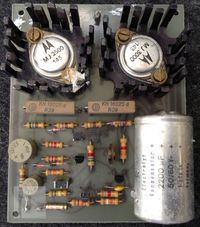
The M35 amplifier was reused to drive a 16Ohms wide-band speaker cabinet by the RT-6SH2P Tube Theremin from a common +40V supply. The pictures show the PCB before restoration.

The M35-AMP can be supplied by up to +44V, according to markings at the printed circuit board (PCB) and has an output power of 35W @ 4Ohms. Because this is a vintage circuit, the used transistor types are widely obsolete. Complementary darlington transistors MJ2500 / MJ3000 are applied in the power-stage. The working point (quiescence-current) is set by R9. Q4 is mounted to the heat-sink of Q8.
The schematic was reconstructed by aetherwellen-musik.de matching the layout and assembly of the PCB. According to Thomsen - Elektronik GmbH, the circuit was designed by the founder of this company, Mr. Boetius Thomsen (decreased in 2008). Information and circuit are provided with approval of Mrs. Karin Thomsen.

| M35 Amplifier Schematic Rev. 1.0 M35 Amplifier Schematic Download M35-AMP_SCH01_1v0.pdf (56.76KB) |
The RT-6SH2P-X Tube Theremin
The RT-6SH2P-X represents the extended version of the RT-6SH2P Tube Theremin. In contrast to the simplified RT-6SH2P Tube Theremin, where the volume is controlled by a Bowden thread, the RT-6SH2P-X enables the player to fully control volume and pitch by the wave of the hands without touching the instrument.


The RT-6SH2P-X Tube Theremin is oriented at the original design of Leon Theremin, applied at e.g. the Rockmore / Rosen theremin instruments (refer to Rockmore/Rosen theremin explanations). It is realized for circuit testing at a modified Kosmos test-board which can hold up to seven 7-pin miniature tubes (only six are used in the RT-6SH2P-X circuit).
This 6SH2P-X Tube Theremin was designed to test the application of 6SH2P (6ж2п / 6AS6 / 6J2P) tubes for generating the Rockmore sound (limited single-sine pulse sound spectrum), applying pitch- and volume control via hand – antenna interaction.

The circuit of the RT-6SH2P-X Tube Theremin as presented in the schematic is discussed below. It represents the 10-2020 version. More detailed descriptions of the electronic principles used by Leon Theremin in his original designs can be found in the Rockmore/Rosen theremin explanations.

| RT-6SH2P-X Tube Theremin Schematic RT-6SH2P-X Tube Theremin Schematic Download RT-6SH2P-X_SCH-BW_0v1.pdf (140.25KB) |
RT-6SH2P-X Tube Theremin Schematic Download
| RT-6SH2P-X_SCH-BW_0v1.pdf (140.25KB) |
The component values largely depend on the characteristics of the inductors, antennas and general assembly of the circuit, thus the given values can only serve as guideline!
The fixed- (V4) and variable (V6) pitch radio frequency (RF) oscillators work in Hartley type configuration, utilizing the 6SH2P (6ж2п / 6AS6 / 6J2P) tubes in triode configuration. They generate sine-signals of approx. 170kHz slightly differing from each other; one frequency controlled by the variable impedance formed by the pitch-antenna ANT2 in conjunction with its extension coil L7, one fixed. Both apply virtually center tapped parallel resonance circuits which can be tuned via adjustable ferrite-cores at the inductors. The pitch can be adjusted by the variable capacitor C27. C27 is connected in series to C30, which reduces it’s capacity an thus the adjustment range for better handling.
 | ") |
") | ") |
The critical pitch antenna extension-coil L7 is wound on a 3D printed multi-section former with adjustable ferrite-core, already designed in 2017. It provides very low distributed capacity and therefore sufficiently high self-resonance frequency (SRF). The rod-antenna is mounted on top of the extension coil to reduce additional lumped capacities from the ‘roof’ connection of the coil to ground.
") | ") |
") | ") |
The phase-detector applies another 6SH2P (6ж2п / 6AS6 / 6J2P) tube V5. The signals of the pitch-oscillators are connected to the control- and suppressor grid via trim-pots (for audio-pulse and pitch linearity adjustment), while the screen grid is supplied by an adjustable voltage, affecting the single-sine audio amplitude at the audio-interstage transformer T1 which is connected to the anode (plate) of V5. The secondary winding of the transformer T1 is connected via trim-pot R14 for pulse width-adjustment of the limited single-sine signal to the voltage controlled AF limiter-amplifier tube V2.
 |  |
 |  |
The value of capacitor C31, which is connected in parallel to the secondary winding, is selected in conjunction with trim-pot R15 (damping of T1 adjustment) to produce the appropriate audio-waveform while forming a parallel resonance circuit with (mainly) the secondary inductance of T1. The limiter-amplifier 6SH2P (6ж2п / 6AS6 / 6J2P) V2 tube’s control grid is grounded because the mutual conductance is too high for correct limiting action. The single-sine pulse is supplied via R14 to the suppressor grid instead. By trim-pot R13, the screen grid voltage of the tube can be adjusted to produce a asymmetrically limited audio pulse at the AF output. The anode is connected via R9 to the volume-control voltage sourced by the Volume-Control Detector tube V3. The output signal supplied to jack J3 is additionally low-pass filtered by R8 and C19, while C22 and R5 form a high-pass filter. The volume of the audio signal can be adjusted by potentiometer R5 (Main Volume). In the test setting, the M35-AMP amplifier, was used to drive a speaker.
")
To control the volume of the instrument, a voltage has to be generated which varies according to the hand movement near the volume antenna. Therefore, the volume-oscillator is frequency modulated (FM) according to the hand movement. This signal is then converted to an amplitude-modulated (AM) RF voltage, which is then demodulated, producing the desired volume-control voltage. The needed circuits and their functions, close to Leon Theremin’s design, are described next.
 |  |
The volume control circuit applies the frequency variable ‘volume’ radio frequency (RF) oscillator (V1) in Hartley type configuration, utilizing a 6SH2P (6ж2п / 6AS6 / 6J2P) tube in triode configuration. It generates a sine-signal of approx. 470kHz. The frequency is controlled by the variable impedance formed by the volume-antenna ANT1 in conjunction with its extension coil L1. The virtually center tapped parallel resonance circuit (L2, C11) can be tuned via adjustable ferrite-core at the inductor. The volume control can be adjusted by the variable capacitor C13. C13 is connected in series to C12, which reduces it’s capacity an thus the adjustment range for better handling.
The critical ‘volume’-antenna extension-coil L1 is wound on a 3D printed multi-section former with adjustable ferrite-core. It provides very low distributed capacity and therefore sufficiently high self-resonance frequency (SRF). The loop-antenna is mounted close to the extension coil to reduce additional lumped capacities to ground.
 |  |
The volume-oscillator’s RF signal present at the grid of V1 is supplied via R4 and C15 to a peak-detector rectifier (Volume Bias Rectifier circuit), consisting of D1, D2, C18 and R6. A large voltage, negative in relation to the Volume Control Detector (V3) tube’s cathode, is developed at R6 and serves as grid bias for V3. A portion of the volume-oscillator’s RF signal, adjustable by trimmer capacitor C16, is passed to the virtually center tapped Volume Control Detector parallel resonator circuit, consisting of the fixed choke L3, the series connected adjustable inductor L4, C21 and trimmer-capacitor C20. The grid of the anode-detector tube V3, utilizing a 6SH2P (6ж2п / 6AS6 / 6J2P) tube in triode configuration, is connected to the virtually tapped inductor (L3, L4) holding the low impedance resonance RF voltage, offset by the negative bias voltage adjustable by R6. The resonator is grounded for RF via C23 and C24. The low impedance connection to the resonator tank is important because V3 draws grid current at maximum RF resonance voltage. Without the virtual tapping, this grid current, loading the parallel L/C circuit, would broaden the resonance curve and thus reduce the sensitivity of the detector to frequency changes of the oscillator. The frequency of the volume-control oscillator changes with the hand movement (FM), and thus the RF amplitude at the resonator (L3, L4, C20, C21) varies accordingly (AM). The resonator is tuned to produce somewhat below maximum amplitude at the frequency which corresponds to the hand removed from the volume-antenna. When the hand approaches the antenna, the frequency is lowered and the amplitude decreases. Thus, the simple circuit converts FM to AM. Trim-pot R6 allows to adjust the negative cut-off voltage of Volume Control Detector tube V3 and thus the volume cut-off of the instrument. V3 performs the AM detection of the volume control RF signal (Infinite-Impedance Detector). A steady residual RF signal is present at the grid of V3 which leads to unwanted conduction of the tube and must be compensated by the offset voltage. R6 is adjusted to a level where the volume-control voltage at the cathode of the detector tube V3 reaches zero with the hand approx. 5 to 10cm away from the volume-antenna. Further approaching the antenna leads up to -20V control voltage. With increasing frequency while removing the hand from the volume antenna, the grid of V3 is loaded with rising RF amplitude (offset by the negative voltage developed by the Volume Bias Rectifier circuit). This leads to more and more conduction of the tube, caused by the positive portions of the RF, shifting the volume-control voltage, developed across C24 (and R12), up to +20V.
")
The anode (plate) voltage of V3 is supplied via the Mute switch, filtered by R11 and C25. In addition, mute indicator bi-color LED D4 is switched accordingly.
The volume control voltage is supplied to the anode (plate) of the voltage controlled limiter amplifier tube V2 and the volume indication instrument M1 (with series connected current limiting resistor R7 and reversal protection diode D3). The control voltage ranges from the negative tube blocking voltage of max. -20V (derived from the volume RF oscillator’s amplitude self-regulation) to approx. +20V, supplied by the Volume Control Detector tube V3.
The volume ‘punch’ when playing staccato, meaning over- and undershoot of the volume control voltage, is inherent to the circuit applying volume antenna-extension coil and detector resonator of high quality factor and low bandwidth, due to LF ringing of the L/C resonators. It may be adjusted by changing the value of C24 and C23 (C23 additionally introduces feedback at fast voltage changes which boost this effect).

The filaments of the tubes are connected in series to be sourced e.g. from the +40V supply voltage via an appropriate 175mA current-source.
") | ") |
To generated the Rockmore like audio spectrum, the correct polarity of the windings of T1, L5 and L6 is essential. In addition, the correct pulse-pause ratio of the output audio-signal (and the linearity of the pitch range) must be adjusted by rotating the pitch oscillator coils to each other and varying their distance.
To adjust the instrument for highest sensitivity, the antenna-extension coils have to be set to max. inductance first. After setting the desired working rest-frequency (hands removed from antennas) by turning the ferrite cores of L2, L6 and L5 (C13, C27 in mid-position), the inductance value of the antenna-extension coils (L1, L7) can be reduced while re-adjusting the oscillator-frequency to the previous value by L2, L6 and L5. This has to be repeated until the desired antenna sensitivity is reached. When frequency jumps occur during inductor tuning or approaching the hand to the antenna, the value of the affected extension coil has to be re-enlarged until no jump occurs any more. In addition, it must be ensured that those jumps do not occur when switching on the instrument. It is better to adjust for lower sensitivity (higher values of the extension-coils) to prevent jumps when changing the position or grounding of the instrument. In general, the sensitivity depends on the L/C-ratio of the oscillator tank. The higher the ratio (L value high, C value low), the more sensitive the antenna becomes when the hand approaches it (Theremin instruments without antenna-extension coils apply a extremely high L/C-ratio to achieve appropriate sensitivity).
FRANZIS Theremin Kit Modification
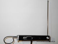
By the German company FRANZIS (FRANZIS Verlag GmbH, Richard-Reitzner-Allee 2, 85540 Haar, Gemany), a Theremin kit is marketed, which is unusable for musical performance because of the worse pitch response and missing volume control. In addition, the possibility to establish a (RF) ground connection is not available, too. The pictures below shows the already modified unit.
The paperboard housing contains a short pitch antenna, a small PCB, volume potentiometer with power switch and a very small speaker. Additional pictures of adjustment knobs are only printed to the front of the housing (!). The unit is supplied by a single 9V battery (which of course lasts not very long). Because of the missing ground, according to the user-manual, the player has to touch a screw which is connected to the unit’s internal ground as long as the FRANZIS Theremin shall be played!

The unit applies two FET Common-Gate Colpitts oscillators of the parallel resonance circuit type. Because of the missing antenna extension coil, the L/C ratio is chosen extremely high to achieve sufficient pitch sensitivity and range. The RF frequency is mainly determined by the self-capacity of the oscillator coils. To worsen the pitch response even more, unfortunately a large part of the antenna is mounted horizontal.
The sound quality, produced by the small speaker, is not worth talking about – of course, non of Leon Theremin’s design principles for creating the Rockmore sound spectrum has been respected (refer to: General Functionality of the Rockmore- and Rosen Instruments according to Leon Theremin’s Design).

To save the Theremin kit from being thrown into the trash can, attempts have been made to convert the unit to a playable nicely sounding Theremin instrument with (simplified) volume control, usable pitch response and grounding facility.
The circuit diagram drafts are presented below as well as pictures documenting the modifications applied to the FRANZIS Theremin kit.


 |  |
 |  |
 |  |
 side") |  |
 |  |
 |  |
 |  |
 |  |
 |  |
 |  |
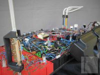
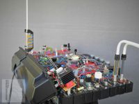
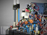
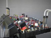
The Rockmorizer Silicon 2017 Theremin
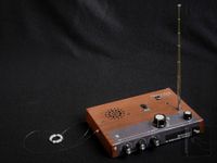
The presented Rockmorizer Silicon Theremin prototype was developed in 2017. It is based on the original design of Leon Theremin, producing the sound spectrum which is assumed to be close to the instrument of Clara Rockmore, applying standard silicon components like transistors, diodes, voltage regulators and op-amps. No tubes are involved. The circuit generates the single-sine audio signal which is formed to rectangular like pulses with appropriate pulse-width to match the desired spectrum. The mechanical construction is based on a sound-bar, including 1W audio power amplifier to drive two small build-in speakers.
The prototype has been disassembled for documentation purposes. It is currently not playable, so there is only a sound file available to hear it’s sound. It was recorded with an improvised binaural microphone headset. The binaural recording technique enables the listener, when wearing headphones, to actually experience the sound impression of the theremin player. In the file, you can hear an interview recording of Clara Rockmore playing quietly at the far right for sound comparison and the Rockmorizer Silicon 2017 theremin somewhat centered or slightly left. In the first part, the internal speakers have been used, in the second part, a large wide-band speaker cabinet was connected, producing a much better sound quality.
The existing schematics have to be transferred from the Electronic Design Automation (EDA) system used in 2017 (provided by a large electronic components distribution company), which has proven to have many drawbacks, to the open source software suite EDA system KiCad. As soon as this work is finished, schematics and layout will be published.
Pictures of the Rockmorizer Silicon 2017 Theremin prototype are shown below.
Additional descriptions under construction!